

The Soul of EDC - From Machine Tools to CNC
Jul 24, 2024
Leave a message
I Background
If there's one professional term that most people hear first when entering the EDC (Everyday Carry) community, it's undoubtedly CNC. This is followed by various high-tech terms such as three-axis, four-axis, five-axis, and precision carving. This article aims to provide a comprehensive yet accessible understanding of what CNC, the soul of EDC, really is (mainly introducing CNC machining centers and CNC wire cutting; more CNC machines will be introduced later).
II Origin
Before diving into CNC, let's first understand two traditional machine tools in the machining industry - the lathe and the milling machine.
▲Manual Lathe Operation
Working Principle of the Lathe: The workpiece is clamped between two centers, and cutting is performed by rotating the workpiece and moving the tool.
▲Manual Milling Machine Operation
Working Principle of the Milling Machine: The tool rotates at high speed to cut the surface of the workpiece. Through video demonstrations, we can see that a manual milling machine controls three movement directions by turning handles: moving the worktable horizontally or vertically (X and Y axes) and moving the worktable vertically (Z axis). The movement of the workpiece allows the rotating tool to machine the surface and depth of the workpiece.
Traditional machining involves manually operating conventional machine tools, with metal being cut by manually turning handles and measuring precision with calipers and other tools. Adding computer numerical control technology to these conventional machines creates CNC machines. CNC stands for "Computer Numerical Control," meaning automated machine tools controlled by a computer. The computer automatically machines products and parts based on pre-programmed instructions, commonly known as CNC machining.
III Title Craftsmanship
At this point, readers should understand how three-axis machining works: the three control directions of the milling machine are managed by a computer. Since the workpiece moves relative to the tool only in the X, Y, and Z directions, each setup can only complete the machining of one face. If another face needs machining, the workpiece must be re-clamped and machined again.
▲Three-Axis Machining DemonstrationMill-Turn Machining Demonstration
The implementation of four-axis machining is quite straightforward: an additional movement direction is provided for the workpiece (the A-axis). The most common machine for achieving four-axis machining is the mill-turn machine. By controlling the rotation of the workpiece around the lathe center (A-axis) and the three-axis movement of the milling cutter (X, Y, Z), the machine completes the machining of the workpiece in a full circle. The difference between a standard four-axis machine and a mill-turn machine lies in their focus: mill-turn machines emphasize the "turning" function, with the A-axis chuck providing sufficient power for machining, while standard four-axis machines use the A-axis primarily for changing the workpiece orientation without providing machining power.
▲DemonstrationMill-Turn Machining Demonstration
Next comes the most advanced-sounding five-axis machining, which is quite clear in its implementation: adding another degree of freedom, commonly referred to as the C-axis. Depending on the model, this can be achieved through dual swiveling heads, dual rotating tables, or a combination of one rotating and one swiveling mechanism.
▲Five-Axis Simultaneous Machining of an Impeller
▲Five Axes in Five-Axis Machining
However, we often hear terms like "pseudo five-axis" and "3+2." What do these mean? The ability to achieve five degrees of freedom does not necessarily mean true "five-axis simultaneous machining." Most machining centers are designed with the option to retrofit additional axes, which is the so-called "3+2" setup. The key feature distinguishing these from true five-axis simultaneous machining centers is "RTCP (Rotational Tool Center Point)." The principle of "3+2" is essentially achieving three-axis functionality at specific angles (i.e., "positioning"), meaning that after the machine has turned to a specific angle, it still operates as a standard three-axis machine. The price difference between these two types of machining is also significant.
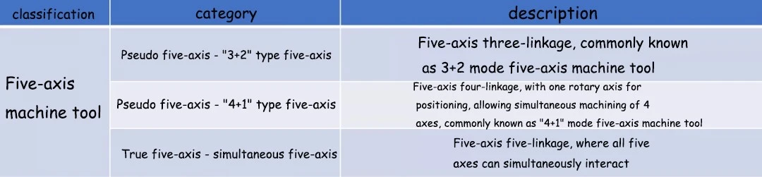
▲Five-Axis Machining with Tool Center Point (TCP) Control
IV Common Problem
Q: Is more axes in CNC machining always better?
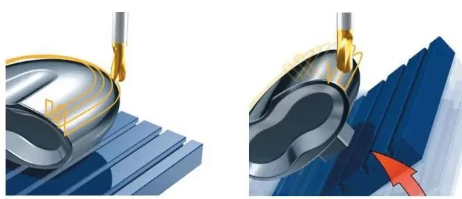
A: In practice, the choice of axes depends on the actual needs of the workpiece. As shown in the illustration, more degrees of freedom can make better use of the tool, improve machining efficiency, and reduce the number of clamping times, leading to less error. However, not all workpieces are suitable for four-axis or five-axis machining. Especially in everyday EDC machining, no design requires the highly complex surfaces, concave areas, or relatively thin surfaces like turbine blades. Therefore, three-axis and four-axis machining can meet most EDC machining needs. The improvement in curved surface quality with 3+2 is minimal, and the cost and benefits of using industrial-grade true five-axis simultaneous machining with RTCP systems are not proportional. It's unlikely that any designer would choose this method.
Q: What kind of designs incur higher CNC costs?
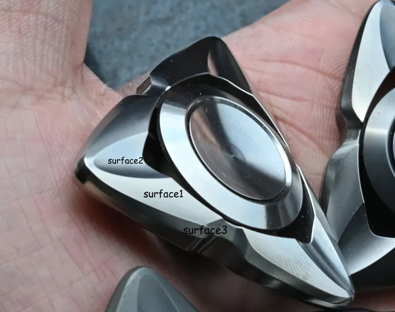
A: First, it's important to clarify that CNC costs are based on machining time. In EDC machining, the most significant factor affecting machining time is the surface complexity. Unlike flat surfaces, curved surface machining requires slow "climbing" with ball-end mills. If two different curved surfaces intersect sharply, slower and more meticulous machining is required to ensure clear edges (chamfers and fillets do not require ball-end mills).
Q: How significant are the precision differences among different machines?
A: Precision in machining is quantified by "tolerance." The tolerance ranges for common milling operations in EDC machining are as follows:
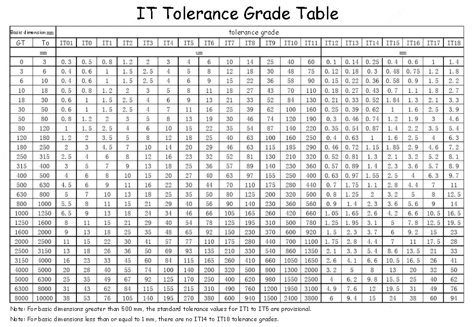
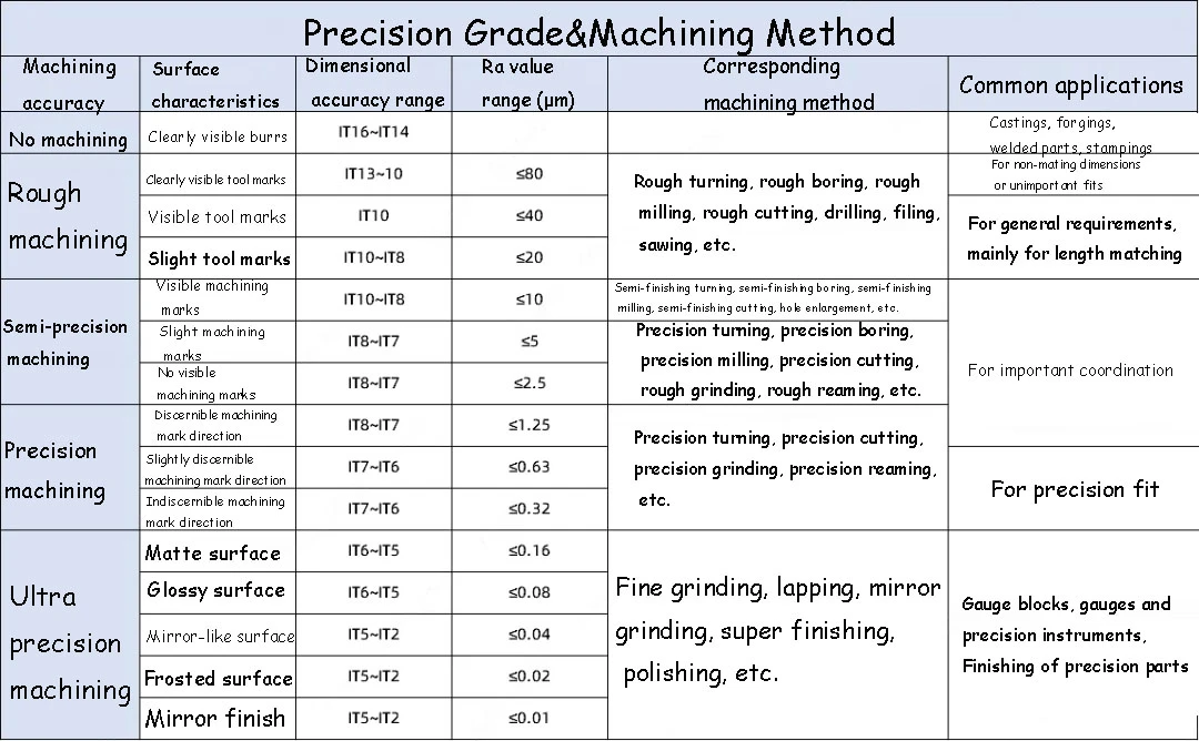
The milling accuracy generally ranges from IT8 to IT7. For rough milling, the processing accuracy is IT11-IT13, with a surface roughness of 5-20μm. For semi-finish milling, the accuracy is IT8-IT11, with a surface roughness of 2.5-10μm. For finish milling, the accuracy is IT7-IT8, with a surface roughness of 0.63-5μm.
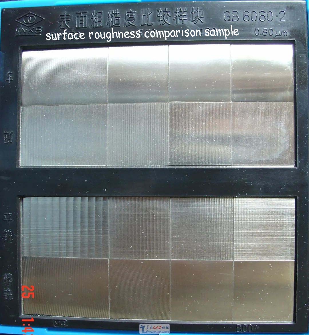
So, what is the precision range for our EDC processing? In fact, most EDC products only require "semi-finish machining," where the product tolerance is around IT8-IT7 and the surface roughness is approximately Rα3.2-1.6. This level of precision is sufficient for the assembly requirements of EDC, such as installing bearings, magnets, and ball grooves. After polishing, the surface roughness can reach Rα0.8. Thus, the machining precision can be visually observed in some grooved tops, and the specific precision values can be determined by comparing "surface roughness samples." It is worth mentioning that processes like stone washing and sandblasting will change the surface roughness of the workpiece. These treatments may increase the surface roughness while preserving enough edges. The specific surface treatment choice should be based on the product characteristics.
IV Cost and Pricing
The main reason the EDC community has remained niche is due to the high prices resulting from CNC costs. But should CNC costs be turned into a selling point themselves? In my opinion, craftsmanship should always serve the product. A good product requires a balance between cost and design. While complex craftsmanship can lead to better presentation, it also brings high prices and long production times. Sometimes, making things overly complicated for the sake of it can deter potential buyers. Of course, a product's reputation depends on many factors, and an excellent design can ignite market enthusiasm, making price a less critical factor. As for you, dear readers, I believe after reading this article, you will have your own answer.