

Effective Methods to Prevent Thin-Walled Pipe Component Deformation in Manufacturing
Nov 05, 2024
Leave a message
In actual production, it is common to encounter the processing of thin-walled pipe fittings of various shapes and sizes, which are prone to deformation during processing. Exploring methods to prevent deformation, ensuring that the parts meet the dimensional and stability requirements, is crucial. Thin-walled components present a challenging issue in turning and milling processes, primarily because of their low rigidity and strength. During processing, they are highly susceptible to deformation, which increases shape and dimensional errors, making it difficult to ensure consistent part quality.
I Main Factors Affecting the Precision of Thin-Walled Pipe Workpieces
1. Susceptibility to Deformation Due to Force
Thin-walled workpieces are highly prone to deformation under clamping forces, which affects both their dimensional and shape accuracy. For example, when using a three-jaw chuck to clamp the outer diameter while processing the inner diameter, the outer diameter can slightly deform into a triangular shape due to the clamping force. Although a cylindrical hole is produced, upon releasing the chuck, the outer diameter recovers to its cylindrical form, while the inner hole becomes arc-shaped or triangular.
2. Heat-Induced Deformation
Cutting heat can cause thermal deformation of the workpiece, making it difficult to control its dimensions. Thin-walled metal components, especially those with high coefficients of linear expansion, are particularly susceptible to thermal deformation induced by cutting heat, which significantly impacts their dimensional accuracy.
3. Vibration-Induced Deformation
Under cutting forces, radial components can cause the workpiece to bend. If the outer surface of the workpiece has features like grooves or notches, the cutting tool may experience uneven forces, leading to vibration. This vibration can negatively impact the workpiece's dimensional, shape, and positional accuracy, as well as its surface roughness.
II Methods to Reduce and Prevent Deformation of Thin-Walled Parts
1. Use of Axial Clamping Fixtures
When turning and milling thin-walled workpieces, it is advisable to use axial clamping rather than radial clamping. The axial clamping method, which utilizes an axial clamping sleeve (threaded sleeve), ensures that clamping forces are distributed along the axis of the workpiece. Since the axial stiffness of the workpiece is higher, this method reduces the risk of deformation.
2. Increasing Clamping Contact Area
Using slit sleeves or specially designed soft jaws increases the contact surface area, which helps distribute the clamping force evenly over the workpiece. This reduces the likelihood of localized deformation during clamping.
3. Optimizing Cutting Tool Geometry and Cutting Parameters
To minimize cutting forces and heat, it is essential to carefully select the geometry of cutting tools and cutting parameters. Lower cutting forces and heat will reduce the likelihood of deformation.
4. Adequate Application of Cutting Fluids
Cutting generates heat, which is primarily concentrated in the chips and cutting tool. Cutting fluids play a crucial role in cooling, lubricating, chip removal, and rust prevention. By adequately applying cutting fluids, the cutting temperature can be reduced, preventing thermal deformation of the workpiece.
5. Adding Process Ribs
Some thin-walled workpieces feature specially designed process ribs at the clamping points to enhance stiffness. The clamping force is applied to these ribs, reducing deformation. After machining, the process ribs can be removed.
III Case Study: Axial Force Application for Turning and Milling Thin-Walled Workpieces
1. Analysis of Thin-Walled Workpiece Difficulty
The material of choice is hard aluminum 2A12T4, and a hollow cylindrical rough material is used. The internal cavity requires milling on four sides, and the outer wall has four large holes (Φ26mm), as well as some assembly-related screw holes and threaded holes. The maximum outer diameter is 180mm ±0.05mm, and the minimum wall thickness is 3mm. The deformation of the roundness must not exceed 0.15mm. In addition to the inherent deformation challenges of thin-walled parts, this workpiece also requires processing of four internal sides and holes on the outer diameter, leading to uneven and asymmetric wall thicknesses that increase deformation. Accurate positioning is required to ensure the precision of the internal and external features.
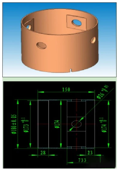
▲ thin-walled parts
2. Pre-Improvement Process Route
1). Turn the internal diameter, rough turn the outer diameter using a three-jaw chuck, and leave a 1mm allowance on both sides for internal and external diameters.
2). Use a machining center to roughly mill the internal cavity with a 1mm allowance on each side, and align the internal faces to rough mill four Φ26 large holes with a 2mm allowance.
3). Stress-relieving treatment.
4). On the lathe, perform secondary rough milling of the inner step with a 0.5mm allowance on each side, and the outer diameter with a 0.5mm allowance.
5). Use the machining center to secondary rough mill the internal cavity with a 0.5mm allowance.
6). Stress-relieving treatment.
7). On the lathe, flat the two end faces to size, perform semi-finish turning of the inner diameter, and finish turn to the final size.
8). Use the machining center to finish mill the internal cavity to size.
9). On the lathe, finish turn the outer diameter to size.
10). Finish mill all outer holes and features on the machining center.
3. Pre-Improvement Process Issues
1). The fixture used for rough and finish milling of the internal cavity was a slit sleeve fixture clamped with a three-jaw chuck. This setup causes radial force on the workpiece, resulting in deformation due to the low rigidity of thin-walled components. The workpiece, during machining, tends to deform into a triangular shape. The clamping force was adjusted during rough milling to release stress, but this caused the workpiece to become unstable, leading to movement or tilt during machining. The toolpath had to be slowed, extending production cycles.
2). For internal turning, specialized brass soft jaws were used for clamping the outer diameter to turn the inner diameter, but deformation still occurred when clamping and releasing the workpiece, due to the workpiece's tendency to absorb cutting heat and release internal stress. The internal and external diameters would shift once the workpiece was removed, making it difficult to control deformation.
3). For finishing the outer holes and grooves, two-point support was used, with clamping force provided by bolts. However, the thin wall and low rigidity caused vibration, especially when drilling, affecting precision.
4. Analysis of Post-Improvement Process Flow
1) Use a three-jaw chuck on the lathe to reverse clamp the inner diameter, perform rough turning on the outer diameter, then re-clamp the outer diameter to rough-turn the inner diameter.
2) Use a machining center to rough mill the internal cavity square and rough mill four large holes with a 1mm allowance on each side.
3) Perform stress-relieving treatment.
4) Use the lathe to flatten both end faces, leave a 0.5mm allowance on the outer diameter, and semi-finish the inner diameter.
5) Perform stress-relieving treatment.
6). Use the lathe to finish both end faces and the inner diameter to final size.
7) Use the machining center to precision mill the internal cavity shape.
8) On the lathe, finish turn the outer diameter to meet roundness and dimensional requirements.
9) Use the machining center to precision mill all external features.
5. Main Processing Methods and Achieved Results Post-Improvement
1) Rough Milling of Internal Cavity
The process of rough milling the internal cavity does not differ from the pre-improvement method. A slit sleeve fixture is used to clamp the outer diameter, while a three-jaw chuck holds the fixture to mill the internal square features. For rough milling the external holes, a special large soft jaw is used to clamp the right end of the workpiece's outer diameter, aligning it with the internal square shape on the left. During precision milling of the internal cavity, the following fixture design (Figure 2 and Figure 3) is used:
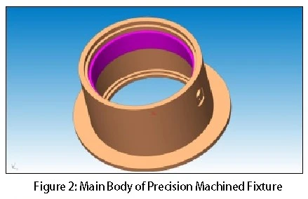
▲ precision milling of the fixture
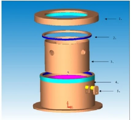
▲ precision milling
Note:
1. Spiral Cap – The spiral cap threads into the light blue part at the upper end of the fixture, securing and compressing the upper part of the workpiece. The through hole diameter of the spiral cap is 2mm larger than the internal diameter of the workpiece, with a workpiece wall thickness of 3mm, creating a 2mm wide compression contact surface. This design does not interfere with the cutting tool's ability to shape the internal cavity of the workpiece.
2. Upper Support Ring – The outer blue wall of the support ring aligns with the upper blue section of the fixture, while the inner wall fits with the workpiece's outer diameter. This prevents movement in all directions (left, right, front, back) of the workpiece's upper end and ensures precise positioning, guaranteeing that the workpiece's rotational center remains consistent with each setup.
3. Workpiece – The workpiece to be processed.
4. Fixture Body (Figure 3) – The lower inside end of the fixture body features a 15mm deep stepped circular groove that fits with the workpiece's bottom outer diameter. The central purple section is made of black rubber material that fits the gap between the fixture and the outer wall of the part to prevent vibration and chatter during machining.
5. Small Stop Block – This part is the key feature of the fixture. It engages with the external groove holes of the fixture body, with the protruding part touching the inner wall of the workpiece's Φ26 circle. This both blocks the workpiece and limits its clockwise rotation. The stop block also plays a crucial role in alignment. Because the tool rotates clockwise, the workpiece is subjected to a clockwise force, which the stop block counteracts. The screw hole and threaded hole of the fixture body firmly secure the stop block, preventing vibration or displacement during processing. The interaction between the small stop block and the inner wall of the workpiece's Φ26 circle is shown in Figure 4.
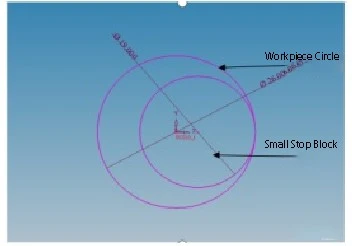
▲ interaction
Achieved Effect:
This fixture only requires minimal axial clamping force from the spiral cap to fully restrict all six degrees of freedom of the workpiece. This ensures that the workpiece is not deformed by radial forces. Additionally, the small stop block itself helps with positioning and alignment, playing a critical role in preventing the workpiece from rotating. The workpiece is securely positioned within the fixture, with a support ring in place for stability, rubber material in the middle for vibration damping, and a 15mm deep stepped circular groove at the bottom for positioning. The system's rigidity is enhanced, which allows for significantly higher cutting parameters, improving overall production efficiency. Before the improvement, this process required 30 minutes; after the improvement, the processing time has been reduced to 15 minutes. Furthermore, this fixture can also be used during precision turning of the internal cavity, reducing overall production costs.
2) Rough and Finish Turning of the Inner Cavity
The fixture designed for rough and finish turning of the inner cavity follows the same principle as the precision milling of the internal cavity. However, the small stop block only serves to limit the rotation of the workpiece, as shown in Figure 5.
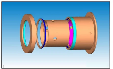
▲ Rough and Finish Turning of the Inner Cavity
The workpiece is axially clamped by the spiral cap, preventing deformation due to clamping forces. When turning the inner hole, the workpiece remains almost completely free, ensuring that the machined hole meets the required technical specifications. Before the improvement, to reduce radial clamping force and prevent deformation, clamping force had to be minimized, which also reduced cutting parameters. After the improvement, there is no need to worry about clamping deformation, allowing for higher cutting parameters and increased production efficiency. The process time reduced from 35 minutes to 25 minutes.
3) Precision Milling of External Wall Holes
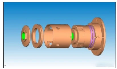
▲ Precision Milling
The fixture for precision milling of the external wall holes is shown in Figure 6. The fixture design focuses on the main body of the fixture at the far right:
Fixture Design: The fixture body is fixed and aligned to the four-axis rotary table. Pre-machined base holes and entry slots prevent tool interference during machining. The light purple section of the fixture aligns with the right-end internal hole of the workpiece, while the left side fits with the internal square shape of the workpiece, providing alignment and preventing rotation. After installing the top and spiral caps, the fixture positions the workpiece securely, eliminating the need for re-positioning. The fixture allows a clearance fit of about 0.03mm between the fixture and workpiece to account for slight workpiece deformation and ensure easy removal.
Effect: During machining, the workpiece remains stable, and there is no unwanted vibration, allowing for higher cutting parameters and improved precision. Compared to the previous fixture, this design reduces setup time significantly, improving system rigidity and ensuring that the workpiece remains stable during processing. As a result, the total machining time has been reduced from 55 minutes to 35 minutes.