

Analysis of Machining Processes and Workpiece Operations
Sep 24, 2024
Leave a message
I. The Relationship between Design and Process
1. Design plays a decisive role in product quality and cost.
2. Designers should have a basic understanding of machining processes and workflows.
3. Process engineers should understand design principles.
4. Design and process must cooperate with each other, respect the facts, and control costs.
Designers (who do not understand machining):
1. Inappropriate material selection
2. Improper heat treatment process, leading to risks
3. Complex machining processes for parts, increasing costs
4. Poor product assembly and maintenance process
Process engineers (who do not understand design):
1. Arbitrarily changing the process structure and part precision
2. Failure to understand the final machining accuracy requirements of parts, creating risks during blanking
A good designer must first understand some common machining knowledge and have a basic understanding of common equipment, such as part sizes and precision. They should also have strong drawing and review skills, an awareness of the entire machining process, and follow up during machining, maintaining full communication with frontline technicians to further optimize the design. Additionally, observing machining processes and methods in the industry can broaden their knowledge and improve their skills.
II. Definition of Machining Process
- Process: Refers to the skills, methods, and procedures used in manufacturing a product.
- Process Flow: The flow that directly changes the shape, size, relative position, and properties of parts, making them finished or semi-finished products. Casting, forging, stamping, machining, welding, and heat treatment processes are all considered process flows.
- Machining Process Flow: The process that uses machining methods.
▲ Machining Process
The process primarily focuses on changing the shape of raw materials, where cast or forged blanks are produced through casting or forging.
The process uses various tools and equipment to machine blanks into parts, mainly altering their shape and size.
The process primarily focuses on determining the relative positions of parts, assembling the machined parts into products according to specific assembly requirements.
III. Common Terminology in Machining Processes
- Operation: A part of the machining process completed by one (or a group of) workers at the same workstation (or machine) on one (or a group of) parts.
- Setup: A part of the machining process completed in one clamping of the workpiece. Setup = positioning + clamping.
- Fixture: A device used to assist in machining.
- Cutting: The process of removing excess material from a workpiece using cutting tools.
- Process Dimensions: Dimensions provided in the process card or drawing as required for machining.
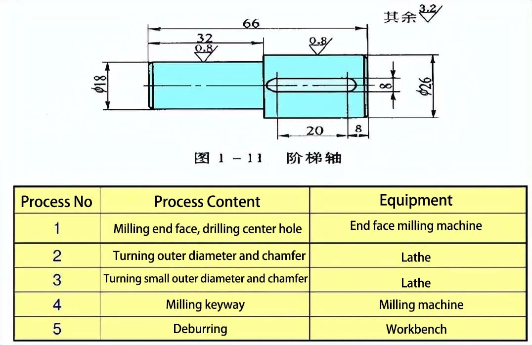
▲ Common Terminology in Machining Processes
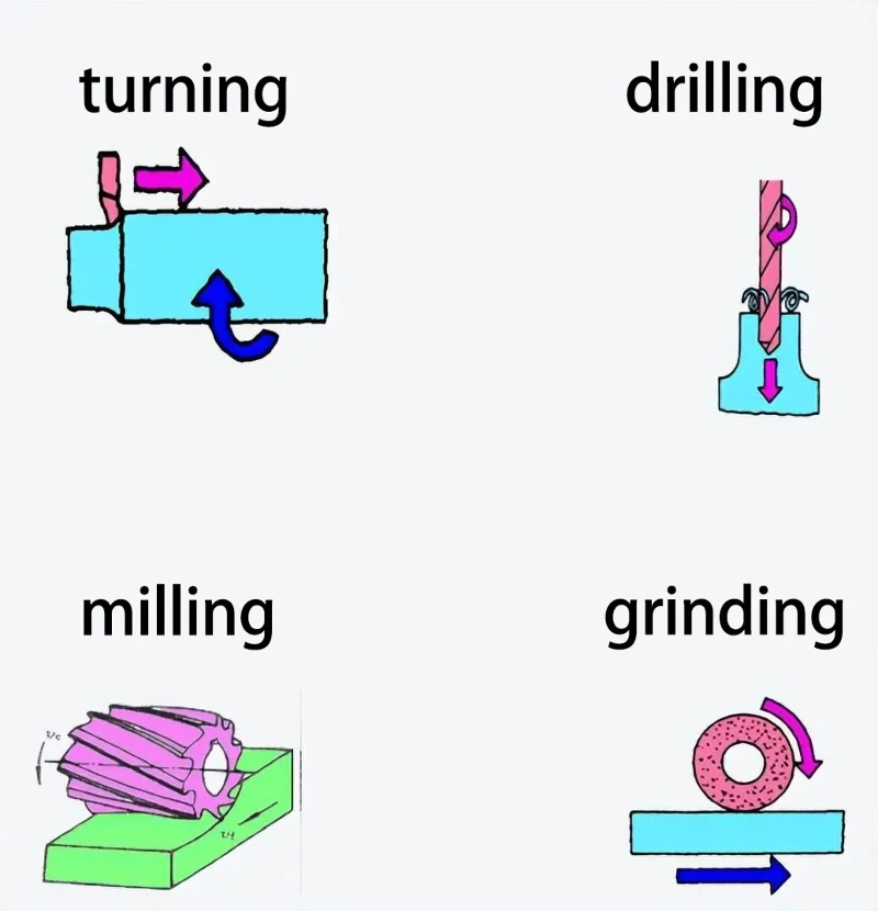
▲ Common Terminology in Machining Processes
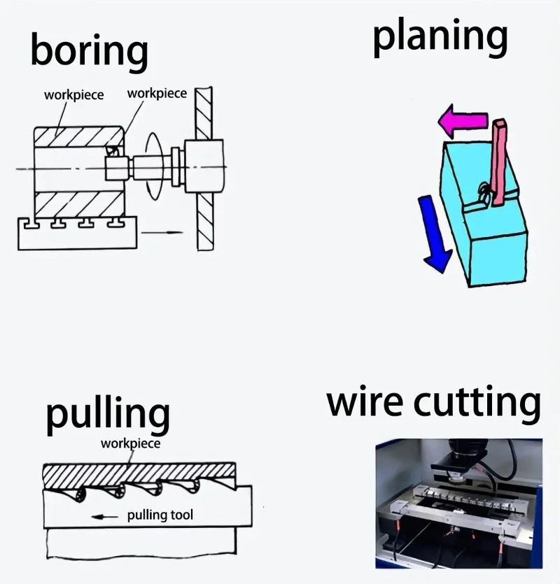
▲Common Terminology in Machining Processes
1. Laser Cutting
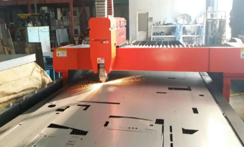
▲ Suitable for thin plates (best for 1.5mm-8mm)
2. Turning
A machining method in which the workpiece rotates as the main movement, and the tool makes feed movements.
The main movement in turning is the rotation of the part, and the linear movement of the tool is the feed movement. It is particularly suitable for machining revolving surfaces.
2.1 Lathe
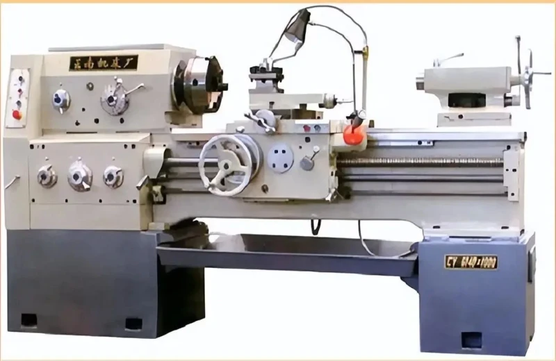
▲ Horizontal conventional lathe (suitable for small batch production)
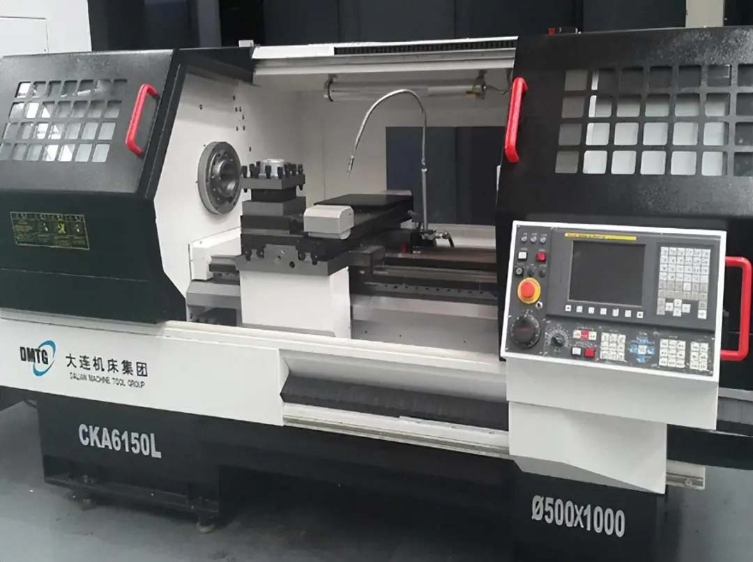
▲ Horizontal CNC lathe (suitable for complex shapes and mass production)
2.2 Turning Application Range
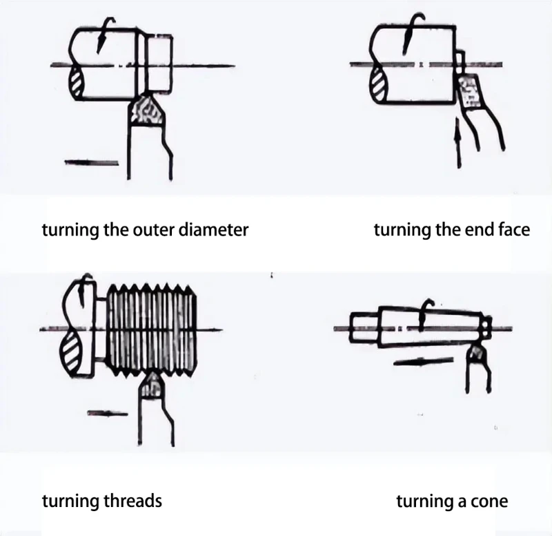
▲ Turning Application Range
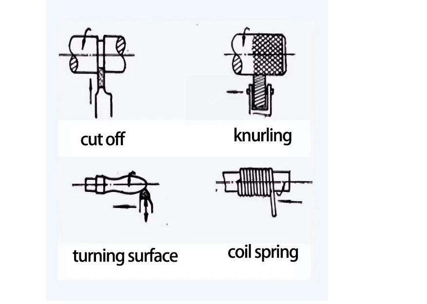
▲ Turning Application Range
3. Milling
Milling is one of the main methods for machining planes. The milling cutter rotates as the main movement, and the workpiece or cutter makes the feed movement.
3.1 Milling Machine
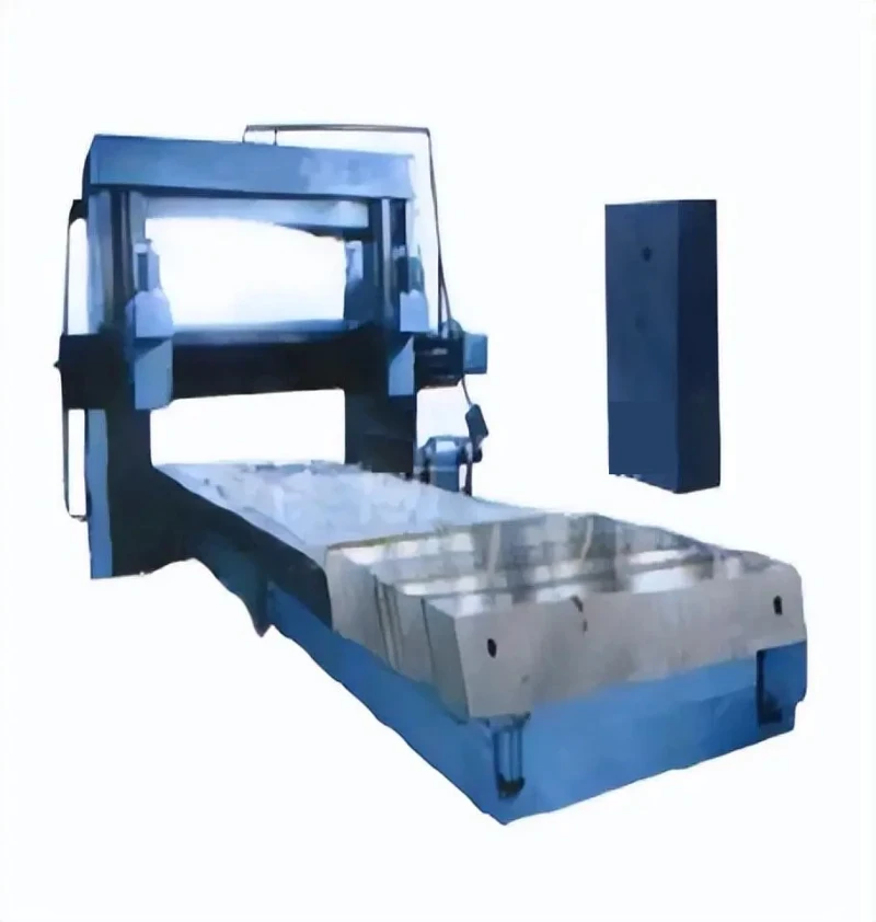
▲ Conventional gantry milling machine
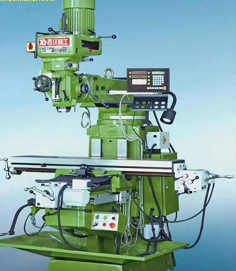
▲ Vertical milling machine
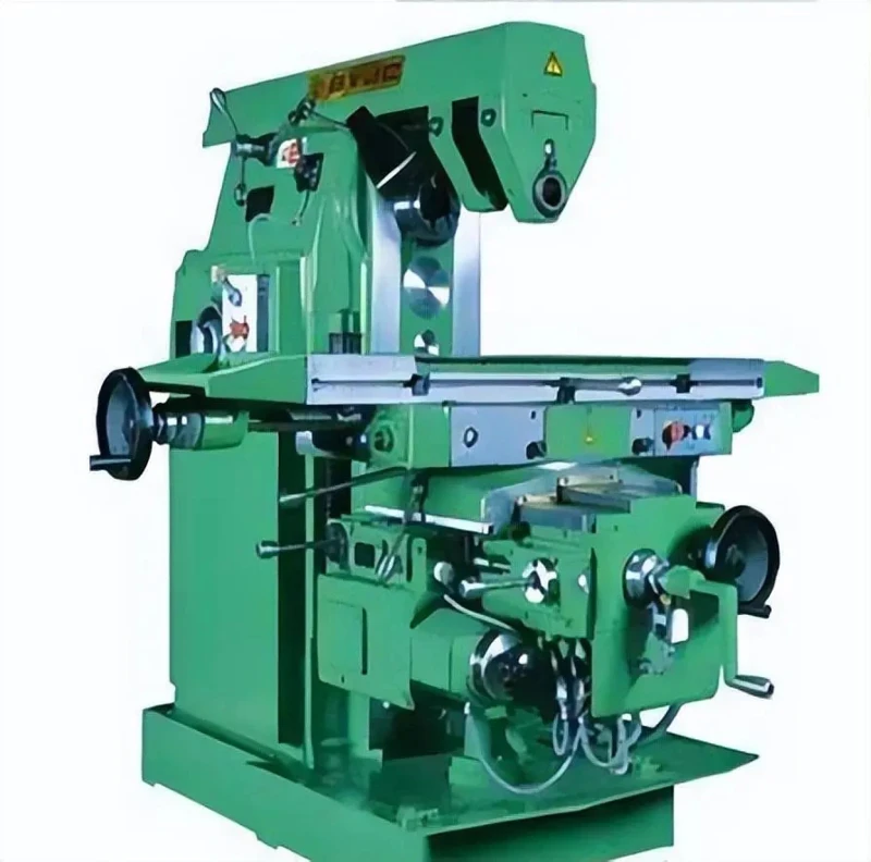
▲ Horizontal milling machine
3.2 Climb Milling and Conventional Milling
Depending on the relationship between the rotation direction of the cutter and the feed direction, milling can be divided into climb milling and conventional milling.
- Conventional Milling: When the cutter rotation direction is opposite to the feed direction, it is called conventional milling.
- Climb Milling: When the cutter rotation direction is the same as the feed direction, it is called climb milling.
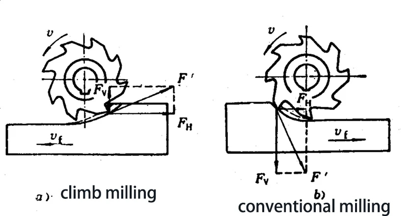
▲ Climb Milling and Conventional Milling
3.3 Advantages of Climb Milling
1. Less likely to cause workpiece vibration, protecting the tool
2. Reduced tool wear
3. High surface quality in climb milling, especially suitable for aluminum alloys
3.4 Applications of Milling
- Milling is mainly used to machine planes (including horizontal, vertical, and inclined surfaces), grooves, forming surfaces, and cutting-off operations.
- Knee-Type Milling Machines (horizontal and vertical): Widely used in small batch production for machining small and medium-sized parts.
- Gantry Milling Machine: Used for machining large and medium-sized parts. Equipped with 3-4 milling heads that can work simultaneously, it is highly productive and widely used in batch and mass production.
- In small batch production, some disc-shaped forming parts can also be processed on a vertical milling machine using a vertical cutter.
4. Drilling
Drilling is a method of machining holes by moving the tool and workpiece relative to each other while the tool feeds axially into the workpiece. Drilling is the most basic hole machining method.
4.1 Drill Press
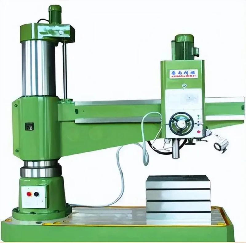
▲ Radial drill press: Only for hole processing (drilling, tapping)
4.2 Applications of Drill Presses
- Bench Drill: Used for small holes (D<13 mm) on small and medium-sized parts in small batch production.
- Vertical Drill: Commonly used for larger holes (D<50 mm).
- Radial Drill: Used for holes in medium and large parts.
- For rotary parts, consider using a lathe or boring machine for hole processing.
IV Analysis of Workpiece Operations
1. Analysis of Workpiece Operations – Example 1
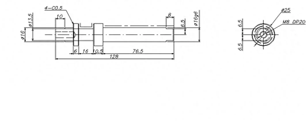
▲ Workpiece CNC drawing
① Blanking: φ25x132 (since there are no outer diameter requirements, φ25 is sufficient for blanking; if there are outer diameter requirements, blank to φ28 and turn down to size).
② Lathe: Drill a center hole and clamp one end with a three-jaw chuck. Turn down φ25, machine step φ16, cut the groove to size φ16 and φ13.5, machine total length, drill the M8 thread bottom hole to a depth of 25, and chamfer.
Clamp φ16, support the other end with the center hole, machine the step to 76.5 and φ16.6 (leaving an allowance of 0.3 for heat treatment deformation), and chamfer.
③ Milling Machine: Mill both ends flat, ensuring the size of 13 (this can also be done after grinding, but wire cutting is the only option).
④Heat Treatment: Surface harden the 76.5 section with high-frequency quenching to HRC40-45, with a depth of 1.5.
⑤ Centerless Grinding: Correct deformation and ensure φ16g6 dimension (if no tolerance requirement for φ16, this step is unnecessary).
⑥ Bench Work: Tap M8, depth of 20, and deburr.
⑦ Surface Treatment: Nickel plating
2. Machining Process – Example 2
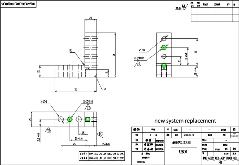
▲ Workpiece CNC drawing
① Blanking: Use ground plates 80x75x25.
② Wire Cutting: Leave 0.5mm for fine milling on surfaces requiring 3.2 roughness, and cut other dimensions to size.
③ Milling Machine:
- (1) Fine mill two vertical surfaces to ensure 3.2 roughness and maintain perpendicularity within 0.02, ensuring dimensions 75, 70, and 20.
- (2) Drilling: Use center drilling, drilling, reaming, and reaming methods to machine 4-φ8H7 pin holes, ensuring size and position, drill 2-φ6.8 threaded bottom holes, 2-φ9 through holes, and maintain center distances of 15, 30, and 45 within tolerance.
④ Bench Work: Tap 2-M8, chamfer, and deburr.
⑤ Surface Treatment: Spray paint (Y07).
3. Machining Process – Example 3
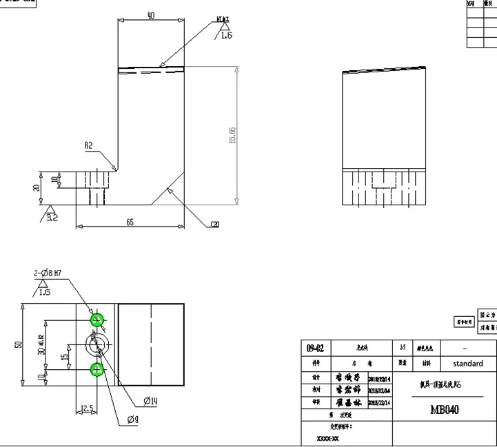
▲ Workpiece CNC drawing
① Blanking: Blue nylon 88x70x55
② CNC Engraving Machine:
- (1) Using A as the reference, attach side A to the worktable with AB glue, then engrave around the profile and form five sides. After forming, machine 2-φ8H7 and φ14-φ9 countersunk holes, ensuring drawing dimensions.
- (2) After engraving five sides and holes, flip and machine side A and chamfer C20.
③ Deburr.
4. Machining Process – Example 4
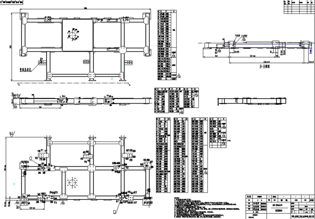
▲ Workpiece CNC drawing
① Straighten after welding, keeping flatness within 2mm.
② Annealing: After annealing, straighten to keep flatness within 2mm.
③ CNC Gantry Milling:
- (1) Calibration and Clamping:Using side A as a reference, place equal-height spacers under side A. Calibrate each point on side B with a height gauge, keeping the entire workpiece flat within 2mm. No gaps are allowed at each clamping point. Use thin shims to fill gaps, and ensure no deformation during clamping. A dial gauge can be used to monitor deformation.
- (2) Rough Milling: Rough mill side B, leaving a fine milling allowance of 1mm. Use a side mill to machine both side surfaces, leaving 1mm on each side. After rough milling side B, flip the workpiece and rough mill side A using the same method, leaving 1mm for fine milling.
- (3) Fine Milling and Clamping: Using side A as a reference, attach it to equal-height spacers with AB glue. Ensure no gaps remain, as direct clamping on the workpiece is not allowed (use jacking where necessary).
- (4) Fine Mill Side B and Both Sides: Ensure flatness. After fine milling, drill holes using center drilling, drilling, reaming, and reaming methods. First, process four reference holes 4-φ10H7, maintaining a hole position tolerance of ±0.02. Once the reference holes are finished, process the other holes according to the program, ensuring dimensional and tolerance accuracy. Machine all side holes using the same method with a side mill, ensuring form, position, and dimensional tolerances.
- (5) After side B is complete, flip and fine mill side A, ensuring flatness. All holes on side A must be machined based on the reference holes 4-φ10H7 on side B. No other reference points should be used. Machine other holes following the program.
④ Bench Work: Tap all threaded holes, deburr, and chamfer.
⑤ Surface Treatment: Spray paint (Y07) on non-machined surfaces, and clear lacquer on machined surfaces.