

Design and Selection of Liquid Cooling Plate Components for Servers
Sep 07, 2024
Leave a message
The liquid cooling plate assembly consists of key components such as the cold plate, connecting pipelines, quick connectors, leak detection devices, and internal coolant.
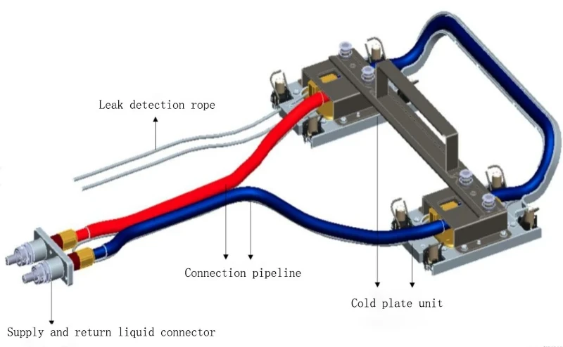
▲ Liquid Cooling Plate Assembly
I Cold Plate
The cold plate is the core component that comes into contact with the processor to enable heat exchange. The coolant flows inside the cold plate to carry away the heat from the processor. Through the connection of pipelines, liquid quick connectors, cooling distribution units, and return manifolds in the cabinet, it forms a secondary closed loop, ultimately transferring the processor's heat outdoors.
1. Structure
Based on the detachability of the heat dissipation module and the fixing module, cold plates can be divided into integrated cold plates and split cold plates. The heat dissipation and fixing modules of an integrated cold plate are inseparable, while in a split cold plate, the modules are detachable through screws.
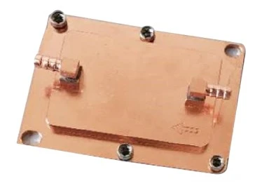
▲ Diagram of an Integrated Cold Plate
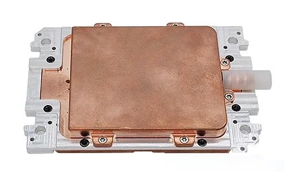
▲ Diagram of a Split Cold Plate
2. Material
Most cold plates in the industry are made of copper, with some manufacturers opting for aluminum, although its use is relatively minimal due to long-term corrosion resistance considerations. A single system should not contain metals with significant potential differences.
3. Design Requirements
- The cold plate should be designed according to the chip's size and the internal structure of electronic equipment to achieve optimal heat exchange efficiency.
- While ensuring the shell temperature requirements of the chip during its entire lifespan, the flow channel design should be optimized as much as possible to reduce the module's flow resistance.
- It should meet the load requirements of the chip socket and the weight requirements for the heat sink.
- The installation and removal sequence of the cold plate should be considered to meet the operational needs of the chip.
- It should also meet the technical requirements for chip clamping force, as well as flatness requirements for the heat sink's bottom surface after installation/removal.
4. Thermal Performance Requirements
- Users should provide the temperature and flow conditions of the coolant at the cold plate's inlet.
- The shell temperature of the cooled chip should not exceed the maximum value specified by the chip supplier during the entire operational period.
- The total flow resistance of the secondary cooling circuit should match the pump's head capability in the cooling distribution unit.
- The total flow resistance capacity of the system and the chip's shell temperature should allow for some redundancy. The flow resistance redundancy should be no less than 10%, and the shell temperature redundancy should be no less than 3°C to accommodate system tolerances.
- Cold plate designers should provide a thermal boundary condition curve for the cold plate, representing the relationship between the inlet coolant temperature and the flow rate of coolant passing through the cold plate.
- The inlet coolant velocity at the cold plate should not exceed 1.5 m/s, and the supply-return temperature difference of the coolant should be controlled within the range of 5°C to 10°C.
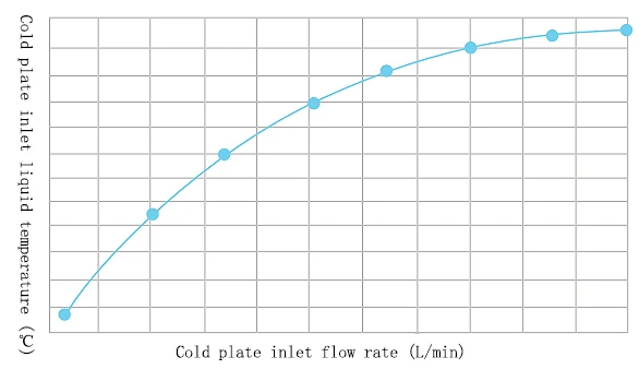
▲ Thermal Boundary Condition Curve for Cold Plate Design
II Coolant
▲ Coolant
Common coolants used in secondary cooling loops include water-based and non-water-based coolants. The choice should satisfy cooling performance requirements while ensuring compatibility and long-term reliability with all wetted materials in the secondary loop. It should also consider IT equipment maintenance, the expected lifespan of the coolant, and overall cost.
Water-based coolants have excellent heat transfer performance, and most of the industry opts for water-based coolants. These are divided into pure water coolants and formulated coolants.
Pure water coolant uses pure water as the solvent without additives, or only a certain proportion of ethylene glycol or propylene glycol as antifreeze, depending on the antifreeze requirements. Pure water coolant inhibits corrosion and microbial growth by maintaining an ultra-low conductivity environment.
Formulated coolants use pure water as the solvent, with a certain proportion of antifreeze added for frost protection, as well as corrosion inhibitors and biocides. Formulated coolants reduce the corrosion risk and inhibit bacterial growth through additives. However, these additives reduce the thermal conductivity of water and may lose effectiveness over time, requiring periodic sampling to monitor the coolant quality.
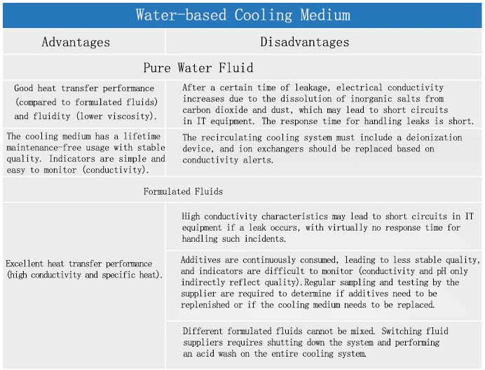
▲ Adwantage and Disadvantage of Water-based Cooling Medium
Based on industry research, Huawei and Sugon primarily use 25% ethylene glycol solutions, while Inspur and H3C mainly use 25% propylene glycol solutions. A concentration of 25% is not fixed; 20% to 30% is acceptable. Too high a concentration may affect fluid flow and cooling performance, while too low a concentration may fail to provide antifreeze protection or inhibit microbial growth. A concentration above 20% generally provides some inhibition of microbial growth for both ethylene glycol and propylene glycol solutions. Therefore, it is recommended to use a 25% concentration of ethylene glycol or propylene glycol solutions as the coolant for liquid cooling systems.
III Quick Disconnect Fittings
Self-sealing quick disconnect fittings (QD) are used to provide fast connections or disconnections between IT equipment and liquid cooling systems for maintenance purposes, while ensuring the coolant does not leak. This ensures the liquid cooling system remains operational, and IT equipment can continue to run safely.
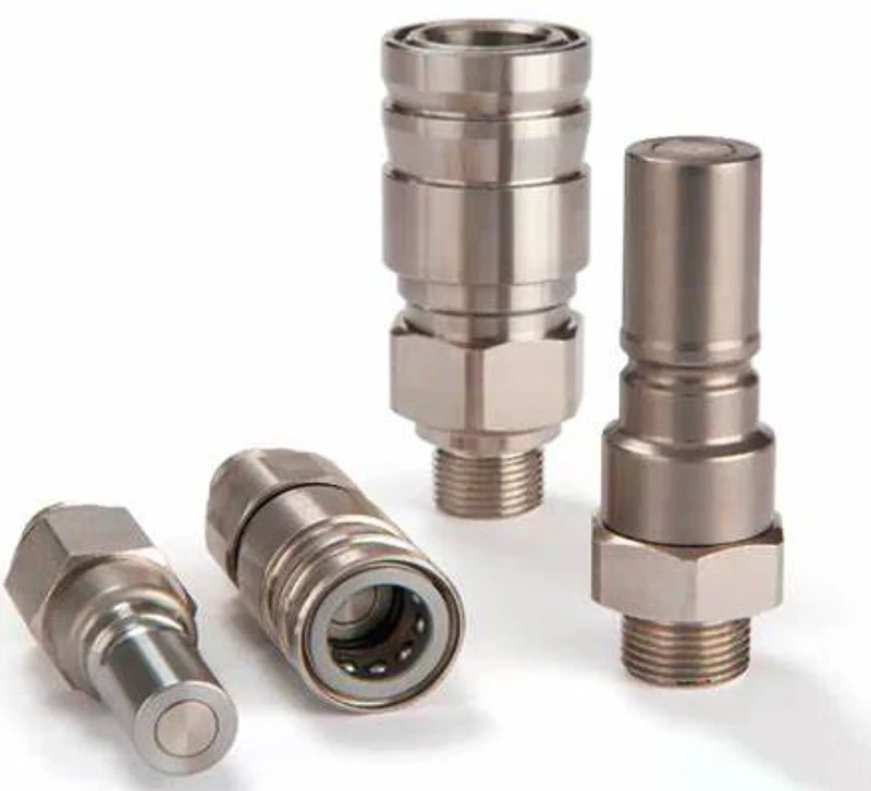
▲ Quick Disconnect Fittings (QD)
There are two main types of self-sealing quick disconnect fittings: manual and blind-mate designs.
Manual quick disconnect fittings require the user to grip the fitting for connection or disconnection operations and can be either single-hand or double-hand operation. Because of the manual operation, sufficient space must be allowed for this.
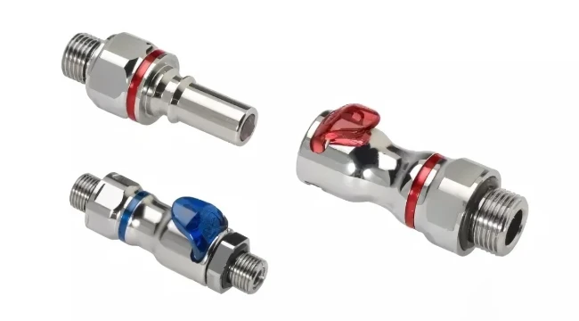
▲ Manual Quick Disconnect Fittings
Blind-mate fittings, which do not require manual operation, connect or disconnect through pressure and need precise alignment with rails or positioning pins to maintain the necessary pressure for proper connectivity, preventing any disconnect.
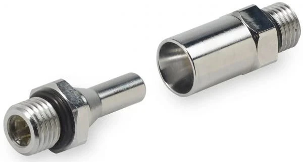
▲ Blind-Mate Quick Disconnect Fittings
Quick disconnect fittings are used in male/female configurations (plug/socket or insert/body pairs). When disconnected, the self-sealing valve within the fitting cuts off fluid flow to protect surrounding equipment. Therefore, the fitting selection must strictly limit coolant leakage during disconnection. Generally, leakage should be less than 1/6 of a drop per connection/disconnection (less than one drop after six connections/disconnections) or less than 0.5 ml. Fittings that minimize leakage, such as those with no-drip or flush-face designs, are recommended.
In systems with manual quick disconnect fittings, ergonomic considerations (e.g., locking mechanisms, connection force, space constraints) should be addressed to ensure ease of maintenance. Blind-mate designs must consider installation tolerances and misalignment tolerance to ensure reliable connection.
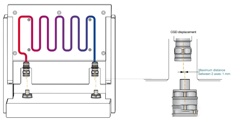
▲ Blind-Mate Alignment Diagram
IV Cooling Distribution Unit (CDU)
The Cooling Distribution Unit (CDU) is a device used for heat exchange between liquid circuits. CDU components include interfaces, pumps, liquid-liquid or liquid-air heat exchangers, reservoirs, valve control devices, monitoring equipment, filters, and various sensors. CDUs are used to measure and control cooling capacity, flow rate, pressure, and temperature. All components in the CDU must be tested for compatibility with the coolant.
CDUs are classified into centralized (cabinet) and distributed (rack) types.
A centralized CDU provides cooling for one or more IT equipment racks or even an entire data center, with greater cooling and supply capacity compared to distributed CDUs. Distributed CDUs eliminate the need for secondary piping installation, with each CDU providing cooling only for the server cabinet in which it is installed, offering lower reliability than centralized CDUs.
To avoid cooling capacity shortages due to CDU failure, N+1 or N+2 redundancy should be considered, or the CDU's pump module should be designed with N+1 redundancy to ensure sufficient cooling for IT equipment and enable online maintenance.

▲ CDU
A comparison of centralized and distributed CDUs is shown in the table below:
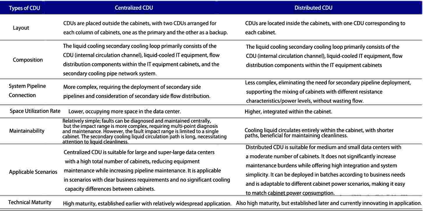
▲ Comparison of Centralized and Distributed CDUs
The heat exchange capacity of a CDU's heat exchanger depends on its approach temperature. The approach temperature is the difference between the temperature of the coolant entering the IT equipment and the primary cooling water temperature at the CDU inlet. Besides approach temperature, other key parameters to consider for CDU performance include:
- Approach temperature (preferably 3-10°C)
- Coolant composition (e.g., pure water, 25% PG, 55% PG)
- Primary and secondary flow rates, pump power, and head
- Primary water temperature grades (e.g., W27, W32, W45, W+)
V Liquid Cooling Pipelines
Liquid cooling pipelines provide the channels for coolant circulation, participating in the flow-resistance distribution of the entire liquid cooling system and providing simple external interfaces for liquid cooling devices. Selection of internal piping for IT equipment must consider material compatibility, flow velocity (which should be controlled below 1.5 m/s in flexible pipelines), piping layout, installation methods, flow distribution design, and reliability.
Liquid cooling pipelines in servers should meet the following technical requirements:
- High-temperature, high-pressure-resistant FEP corrugated or EPDM hoses should be used, with working pressure ≥ 0.35 MPa and maximum pressure ≥ 1 MPa.
- Leak detection ropes should be installed to detect any coolant leaks.
- Pipelines should be connected to the cold plate using barb fittings or hose clamps to ensure a reliable seal.
1. Main classifications of liquid cooling pipelines
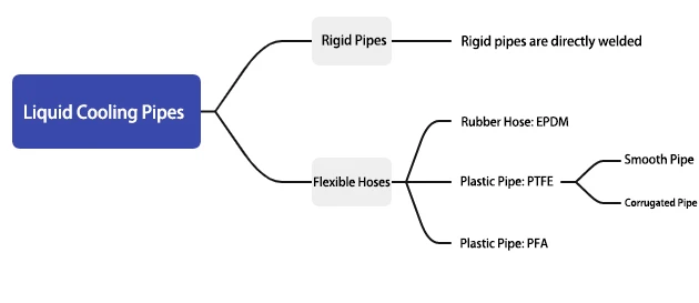
▲ Liquid Cooling Pipeline
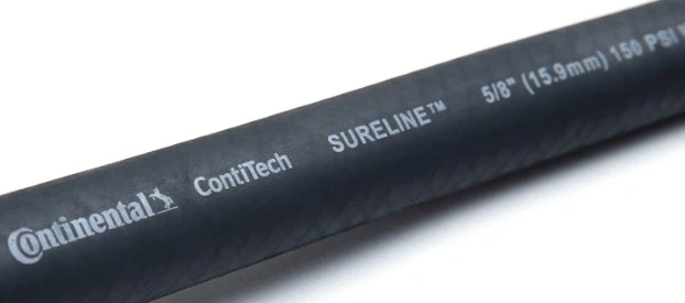
▲ EPDM (Ethylene Propylene Diene Monomer) Hose
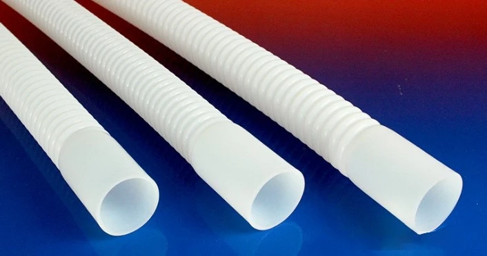
▲ PTFE (Polytetrafluoroethylene) Corrugated Pipe
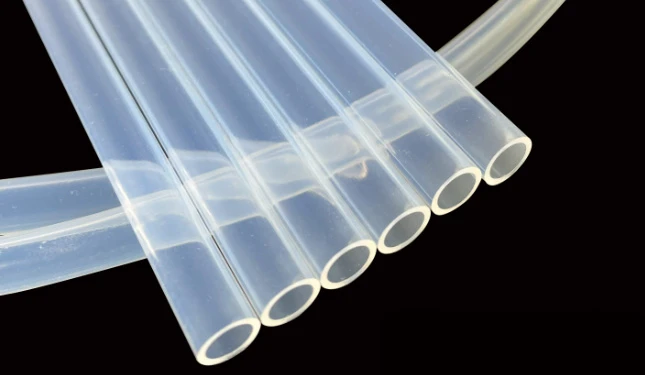
▲ PFA (Perfluoroalkoxy Polymer) Pipe
2. A comparison of different pipeline materials
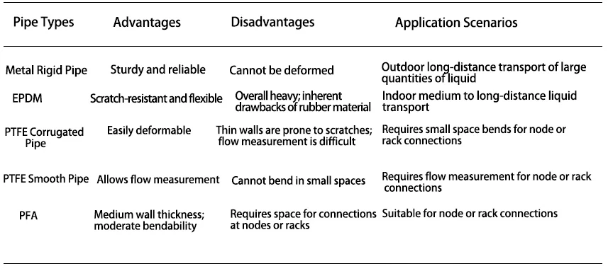
▲ Pipeline Materials
VI Leak Detection Rope
Since computing nodes are often the most expensive components in IT equipment, and there is a risk of conductive coolant leaks that may cause equipment damage and data loss, it is necessary to detect potential leaks inside the computing nodes. Leak detection is generally classified into two methods: indirect and direct.
1. Detection Method
Indirect Method: Leak detection is determined using existing sensors and algorithms for pressure, flow rate, temperature, and bubbles.
Direct Method: Sensors such as leak detection ropes/cables or membrane detection strips are used at specific locations (e.g., along pipelines and joints) to directly detect leaks.
At present, the industry mainly adopts the direct method, using leak detection ropes for leak detection.
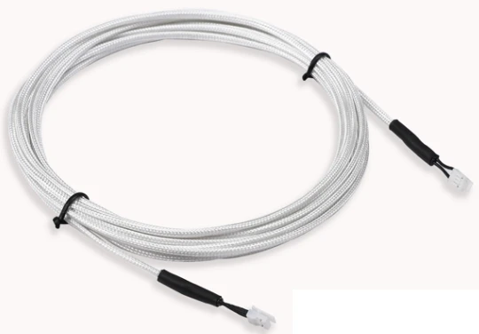
▲ Leak Detection Rope
2. Detection Principle
Leak detection ropes are based on the principle of liquid conductivity to detect whether a leak has occurred and must be used in conjunction with a water leakage controller. When any part of the detection rope comes into contact with water, the two sensing lines will short-circuit. The water leakage controller determines the leakage condition based on the change in the detection rope's resistance and sends an alarm signal.
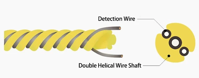
▲ Detection Principle of Leak Detection Rope
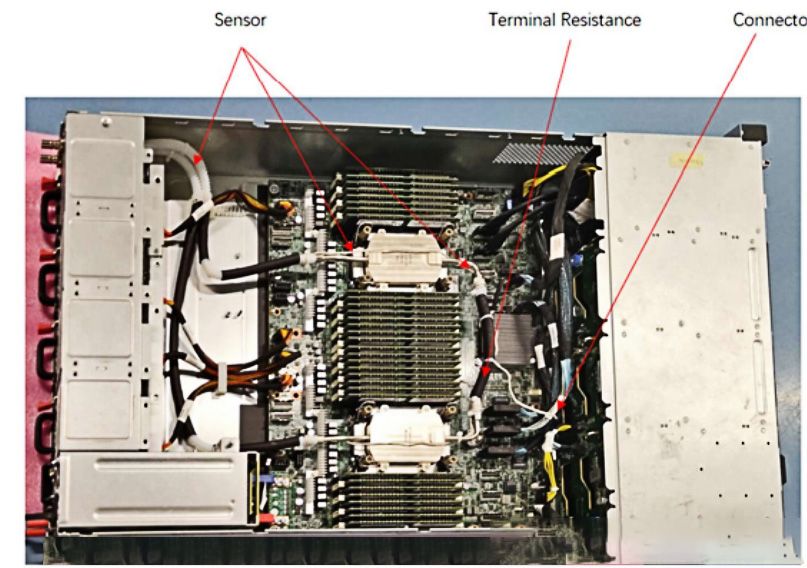
▲ Layout of Leak Detection Rope Inside a Server
3. Precautions During Leak Detection Rope Installation
- The sensing line should remain dry and clean during installation.
- Avoid laying the sensing line in areas prone to condensation.
- Overlapping or intertwining of the sensing lines is prohibited, as this may cause false alarms.
- The bending radius of the sensing line during installation should not be less than 4mm (as per a commonly used wire), or the sensing line may become damaged.
- When installing the sensing line in a coiled manner, avoid a winding radius of less than 24mm, as this may damage the sensing line.
- The sensing line should not be installed in environments with high temperatures, high humidity, vibrations, corrosive gases, or other sources of electronic noise interference.
- During installation or use, do not squeeze or place heavy objects on the sensing line, as this may cause damage.
- Avoid excessive tension on the sensing line during installation, as this may loosen the wire connection ends, cause poor connections, breakage, or detachment of terminals.
- If the leaked liquid contains conductive substances or water-resistant pollutants (e.g., wax, oil), it may cause the sensing line to fail to reset, in which case the sensing line will need to be replaced.