

Exploring Different Milling Techniques for Precision Machining
Nov 11, 2024
Leave a message
I Milling Methods
1. Basic Milling Processes
These include: face milling, slot milling, side milling, and profile milling.
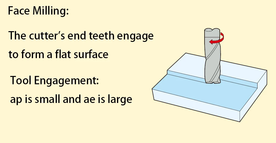
▲ Face milling
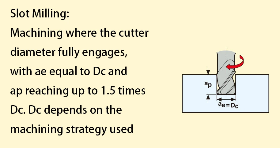
▲ Slot milling
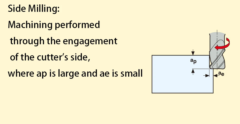
▲ Side milling
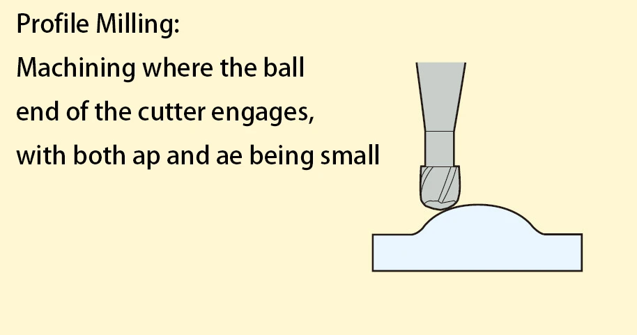
▲ Profile milling
2. Advanced Milling Processes
Advanced milling methods include: ramp milling, thread interpolation, cycloidal milling, push-pull profile milling, interpolation milling, constant contour milling, and drilling.
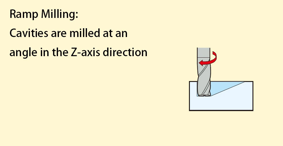
▲ Ramp milling
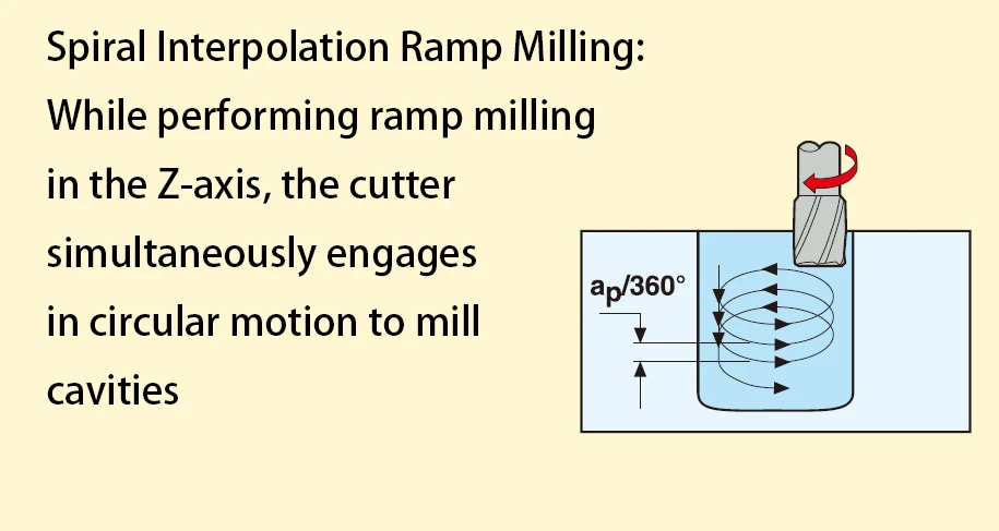
▲ Thread interpolation
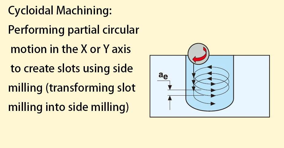
▲ Cycloidal milling
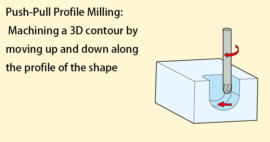
▲ Push-pull profile milling
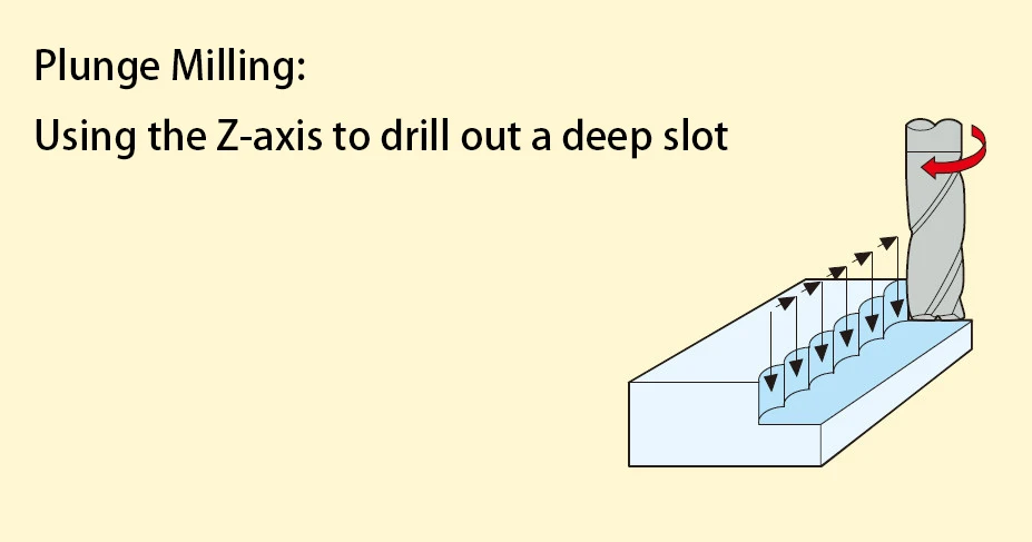
▲ Interpolation milling
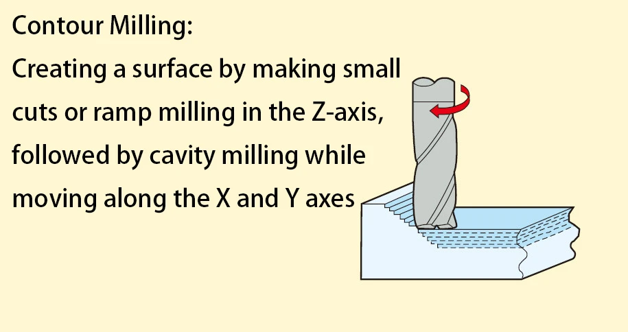
▲ Constant contour milling
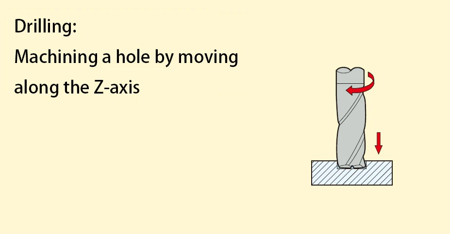
▲ Drilling
II Definition of Milling Strategies
1. Conventional Milling
Conventional milling is a standard machining strategy for general purposes. The cutting width-to-depth ratio can vary depending on the operation type.
1) Tool Characteristics: The tool has relatively long cutting edges and a small core diameter, with no high precision requirements.
2) Machine Requirements: No specific machine requirements.
3) Applications: Suitable for basic CNC technology; advanced methods are not feasible. Metal removal rates are typically moderate. Applications generally include small-scale batch production and a wide range of materials.
2. High-Speed Milling
High-speed milling combines small radial cutting depths with high cutting speeds and feed rates. It enables high material removal rates and lower Ra values. Typical features of this strategy include low cutting forces, reduced heat transfer to the tool and workpiece, minimized burr formation, and high dimensional accuracy. By using faster cutting speeds than conventional milling, high-speed milling can achieve high metal removal rates and good surface finish.
1) Tool Characteristics: Stable tools (larger core diameter and shorter cutting length), well-formed chip spaces for good chip removal, coatings.
2) Machine Requirements: High-speed CNC control, high spindle speeds, and fast table feed rates.
3) Applications: Used in mold industry for semi-finishing and finishing hardened steel (48-62 HRC) with short delivery times. When the correct tools and advanced techniques are applied, it can also be used for other materials.
3. High-Performance Milling
High-performance milling is a machining strategy that achieves extremely high material removal rates. Typical characteristics of this strategy include a cutting width equal to 1x the diameter (Dc) and cutting depth between 1 and 1.5x the diameter (Dc), depending on the workpiece material. High-performance milling uses cutting methods with significantly higher chip loads than conventional milling, enabling high material removal rates.
1) Tool Characteristics: Chip removal structures specifically developed for tool flutes, 45° tool tips, small flat faces or rounded tips for protection, ultra-smooth chip spaces, coatings, with or without side-lock shanks.
2) Machine Requirements: High stability, high power requirements, high rigidity clamping systems.
3) Applications: Key in mass production with efficiency as a critical metric, or for single-part machining that requires high metal removal rates.
4. High-Feed Milling
High-feed milling combines full-diameter cutting with small cutting depths for high feed rates. This method achieves high metal removal rates and good surface finish through faster feed speeds compared to conventional milling.
1) Tool Characteristics: Specially developed tool tips, very short cutting lengths, coatings.
2) Machine Requirements: High stability and capability for high feed rates.
3) Applications: Suitable for soft steel, hardened steel, titanium alloys, and stainless steel. It is excellent for pre-processing before high-speed milling or for deep cavity machining. One advantage of high-feed milling is the ease of programming in CAM systems, allowing for simple, safe, and rapid programming of complex shapes without extensive programming experience.
5. Micro Milling
Micro milling uses extremely small tool diameters for precision machining.
1) Tool Characteristics: Tool diameters range from Ø0.1mm to 2.0mm, short cutting lengths, a wide range of outer diameter reductions, high precision, and coatings.
2) Machine Requirements: High spindle precision, high speed, CNC, thermal stability to prevent spindle elongation.
3) Applications: Used for various cavity machining across a wide range of materials.
III Milling Parameters and Calculation Formulas
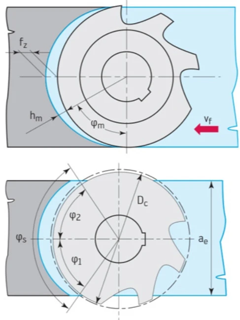
▲ Milling Parameters
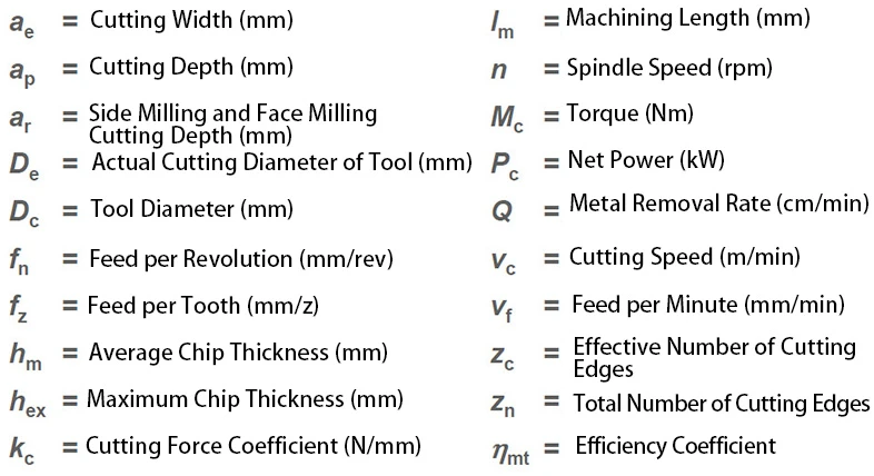
▲ Parameters
Cutting parameter calculation formulas:
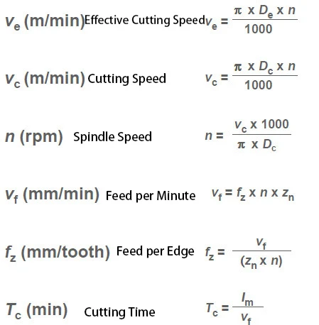
▲ Calculation formulas 1
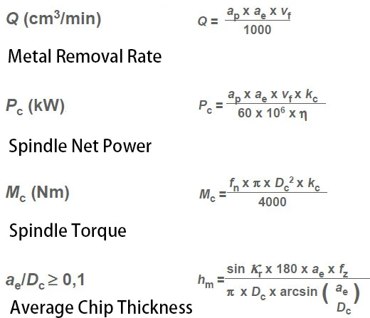
▲ Calculation formulas 2
IV Milling Summary
1. Check the machine power and rigidity to ensure the milling cutter diameter has the shortest possible overhang when using the tool on the machine.
2. The number of teeth on the cutter should be appropriate to avoid excessive simultaneous engagement with the workpiece, which can cause vibration. When milling narrow workpieces or cavities, ensure enough teeth engage with the workpiece.
3. Use the appropriate feed per tooth to ensure a good cutting effect with sufficient chip thickness to reduce tool wear. Use positive rake angle inserts to achieve smooth cutting and the lowest power consumption.
4. Select the milling cutter diameter that suits the workpiece width.
5. Use the correct primary cutting angle (45° is typical for general milling).
6. Position the milling cutter correctly.
7. Use cutting fluid only when necessary. Dry milling often results in longer tool life.