

How to Choose the Best Compact Heat Exchangers for Electronics Cooling
Oct 16, 2024
Leave a message
The use of high-power-density components in electronic products is rapidly increasing, making liquid cooling a viable solution for high heat flux applications, which is currently a major trend. Among other factors, an effective liquid cooling system relies on the heat dissipation capacity of its heat exchanger. These heat exchangers vary in type, size, and configuration depending on the application scenario.
I Basic Construction
Figure 1 shows a typical water-to-air, liquid-cooled, closed-loop system. The coolant is pumped through a cold plate in contact with the IC components. The heat absorbed from the components is dissipated into the air through the heat exchanger, and the cooled liquid continues through the loop, repeating the cycle.
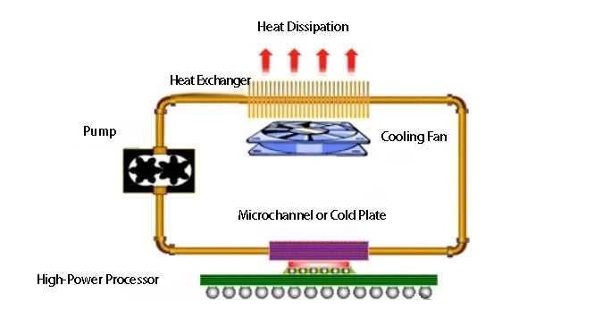
▲ Figure 1. Water & Air Hybrid Cooling Loop for Electronic Devices
The formula for calculating the heat transferred from water to air is as follows:

Where:
- Tw2: the temperature of the fluid entering the heat exchanger;
- Ta: the surrounding air temperature of the heat exchanger;
- Cmin: the smaller of the heat capacity rates of air (Ca) or water (Cw), which is the product of mass flow rate and specific heat at constant pressure;
- ε: the effectiveness of the heat exchanger, defined as the ratio of actual heat transfer in the heat exchanger to the maximum possible heat transfer thermodynamically.
The surface temperature of the IC components in contact with the cold plate is calculated using formula 2.

Where:
- Tw1 is the water temperature at the inlet of the cold plate;
- Rcp is the thermal resistance from the IC components to the cold plate inlet, including the interface resistance between the components and the cold plate.
The temperature rise in the water due to the heat from the components can be estimated using the following formula:

Where: Cw is the heat capacity rate of the liquid, which is the product of mass flow rate and the liquid's specific heat.
By integrating formulas 1-3, we derive formula 4:

This links the surface temperature of the IC components to the performance of the cold plate and heat exchanger.
In the above equations, if different fluid types are used in the heat exchanger, the subscripts "w" and "a" should be changed to general subscripts "c" and "h" to represent the properties of the cold and hot fluids, respectively.
Heat Exchanger Surface Area
The surface area of the heat exchanger must be very large, especially on the side exposed to air. This is because the heat transfer coefficient in air cooling is much lower than in liquid cooling. Increasing the surface area on the air side reduces thermal resistance, allowing for higher heat transfer between liquid and air.
Despite the need for large surface areas to effectively dissipate heat, many projects do not have enough space to accommodate large heat exchanger units, especially in device-level applications for components and boards.
Choosing the appropriate heat exchanger within the available space is critical. Additionally, parameters such as mass flow rate, using liquids with higher specific heat, or increasing cooling fan power can be adjusted to improve cooling performance.
II Heat Exchanger Fin Types
The air side of heat exchangers is typically fitted with compact fins to increase heat exchange between air and liquid.
The type of fins must be appropriate for the specific application scenario. The book Compact Heat Exchangers introduces several fin types, including straight fins, louver fins, strip fins, wavy fins, and pin fins, as shown in Figure 2.
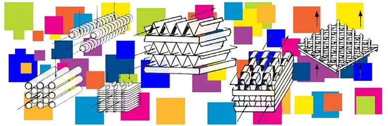
▲ Figure 2. Types of Heat Exchanger Fins
Studies have tested air-cooled heat exchangers and provided guidelines for optimizing fin design by combining heat transfer, pressure drop, size, weight, and cost.
The correlations for using the Colburn factor (JH) and friction factor (f) to describe the heat transfer index and pressure drop index are shown in formulas 5 and 6.
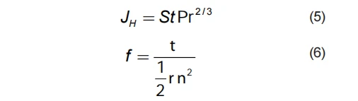
Where: ρ and v are the fluid's density and kinematic viscosity.
The Stanton number (St) in formula 5 can be rewritten as follows:

In formulas 5-7, Pr, t, v, NU, and Re represent the Prandtl number, wall shear stress, kinematic viscosity of the fluid, Nusselt number, and Reynolds number, respectively.
Figure 3 shows the relationship between the (JH/f) ratio and Reynolds number for the fin structures shown in Figure 2.
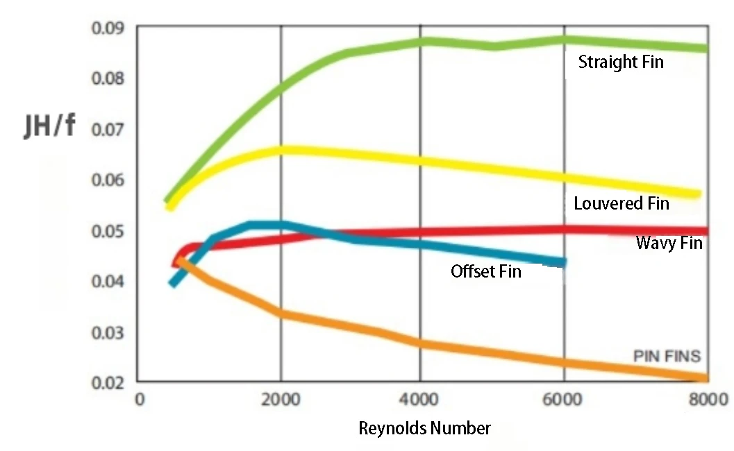
▲ Figure 3. Relationship Between Fin Structures and Reynolds Number
It can be clearly seen from Figure 3 that when the key design factor of the heat exchanger is the heat transfer per unit of pressure drop, straight fins are the most efficient, followed by louver, wavy, offset strip, and pin fin structures.
Under various airspeed conditions, the thermal resistance of the straight fins was the lowest.
In Figure 4, the heat transfer per unit height and Reynolds number ratio indicates that pin fins are the most suitable configuration, followed by louver, offset strip, wavy, and straight fins.
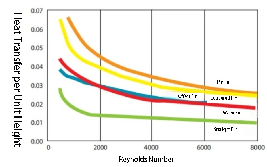
▲ Figure 4. Heat Transfer Per Unit Height for Different Heat Exchanger Configurations
Another important design factor is weight. For example, optimizing heat exchangers used in avionics systems often prioritizes louver fins first, followed by wavy, offset strip, pin, and straight fin designs.
III Compact Heat Exchanger Coolant
Depending on the system and application, small heat exchangers use different types of fluids. Certain fluids have greater heat transfer and more effective thermal diffusion per unit volume.
To illustrate this, consider heat transport due to enthalpy change in an open system, as shown in formula 8.

Where:

(ρ is the fluid density, V is velocity, and A is the cross-sectional area), Cp is the specific heat at constant pressure.
If velocity and cross-sectional area are considered constants, Cp and ρ determine the heat transfer when using different fluids.
Table 1 shows the values of Cp, ρ, μ, and k for ethylene glycol, water, and air at 300K.
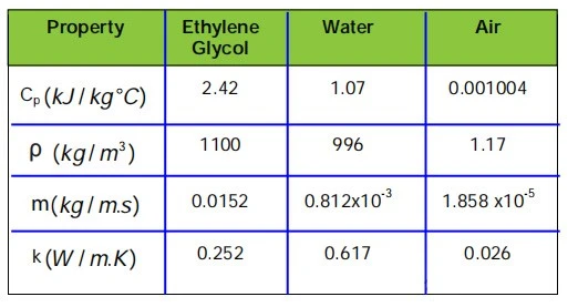
▲ Table 1. Thermodynamic Properties of Typical Coolants
Table 1 shows that fluids with higher density and heat capacity can remove more heat. Using such fluids significantly increases heat transfer in high heat flux applications.
However, using liquids with better heat transfer capabilities requires higher pump power to drive the fluid through the system.
To reduce the power required for coolant circulation, the heat exchanger uses boiling heat transfer.
In some systems, the coolant absorbs heat from the heat source and evaporates.
Based on system complexity, the hot coolant is pumped through a finned condenser section, where the coolant is cooled and returns to the liquid phase.
Since the coolant changes phase from liquid to gas and becomes lower in density, the required pumping power for coolant circulation is greatly reduced.
As integrated circuits rapidly advance, with components having higher power density, compact heat exchangers are becoming essential in electronic cooling solutions.
To fully utilize these devices, it is important to understand their concepts, benefits, and limitations. To correctly use heat exchanger systems, design factors such as pressure drop, heat transfer, size, weight, and cost must be prioritized.