

22 Essential Facts You Must Know About CNC Engraving Machine Processing!
Jul 27, 2024
Leave a message
CNC engraving machines excel in fine machining with small tools, capable of milling, grinding, drilling, and high-speed tapping. They are widely used in the 3C industry, mold industry, medical industry, and other fields. This article collects common questions about CNC engraving processing.
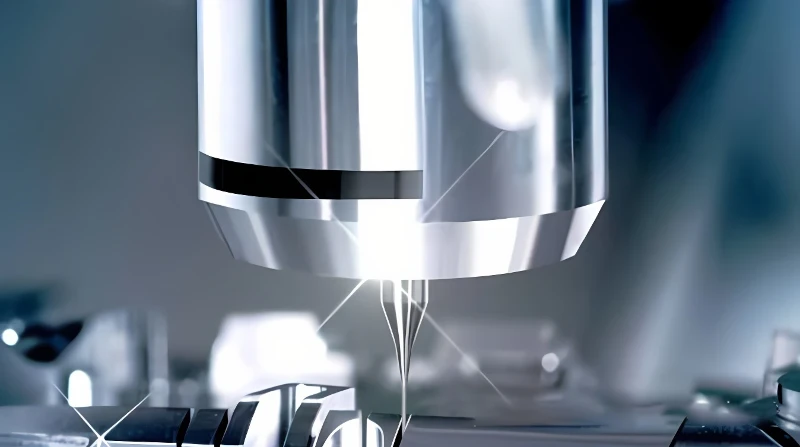
1. What is the main difference between CNC engraving and CNC milling?
Both CNC engraving and CNC milling use milling principles. The main difference lies in the tool diameter used. The typical tool diameter range for CNC milling is 6-40 millimeters, while for CNC engraving, it is 0.2-3 millimeters.
2. Is CNC milling only for rough machining and CNC engraving only for fine machining?
Before answering this, let's understand the concept of the process. Rough machining involves a large amount of material removal, while fine machining involves a small amount. Therefore, some people habitually think of rough machining as "heavy cutting" and fine machining as "light cutting." In reality, rough machining, semi-finishing, and finishing are process concepts representing different stages of machining. So, the correct answer is that CNC milling can perform both heavy and light cutting, while CNC engraving can only perform light cutting.
3. Can CNC engraving perform rough machining on steel materials?
To determine if CNC engraving can process a certain material, the tool size must be considered. The tools used in CNC engraving determine its maximum removal capacity. If the mold shape allows the use of tools with a diameter greater than 6 millimeters, it is strongly recommended to first use CNC milling and then use engraving to remove the remaining material.
4. Can a CNC machining center with a speed increaser perform engraving?
No, it cannot. Such products appeared at exhibitions two years ago but could not complete engraving. The main reason is that CNC machining centers are designed with their own tool range in mind, and the overall structure is not suitable for engraving. The misconception arises from equating high-speed electric spindles with the sole feature of engraving machines.
5. Can CNC engraving replace EDM (Electric Discharge Machining)?
No, it cannot. Although engraving reduces the tool diameter range for milling, allowing some small molds that previously required EDM to be processed with engraving, the length-to-diameter ratio of engraving tools is generally around 5:1. When using small diameter tools, only shallow cavities can be machined, while EDM can produce cavities with almost no cutting force, as long as electrodes can be manufactured.
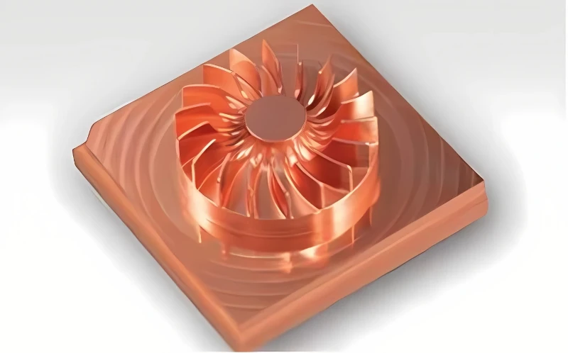
6. What are the main factors affecting engraving processing?
Machining is a complex process with several influencing factors, mainly including machine tool characteristics, tools, control systems, material properties, processing technology, auxiliary fixtures, and the surrounding environment.
7. What are the requirements for the control system in CNC engraving processing?
CNC engraving is fundamentally a milling process, so the control system must have milling capabilities. For small tool processing, it must provide a feedforward function, decelerate in advance of the path, and reduce the frequency of tool breakage. Simultaneously, the feed speed should be increased on smoother path segments to improve engraving efficiency.
8. What material properties affect processing?
The main factors affecting the engraving performance of materials are material type, hardness, and toughness. Material types include metallic and non-metallic materials. Generally, the greater the hardness, the poorer the machinability; the greater the viscosity, the poorer the machinability. More impurities also reduce machinability, and the greater the hardness of internal particles, the poorer the machinability. A rough standard is that higher carbon content leads to poorer machinability, higher alloy content leads to poorer machinability, and higher non-metallic element content leads to better machinability (though the non-metallic content in materials is generally strictly controlled).
9. Which materials are suitable for engraving?
Suitable non-metallic materials for engraving include acrylic, resin, and wood. Unsuitable non-metallic materials include natural marble and glass. Suitable metallic materials include copper, aluminum, and soft steel with hardness less than HRC40. Unsuitable metallic materials include hardened steel.
10. How does the tool itself affect processing, and in what way?
Factors affecting engraving tool performance include tool material, geometric parameters, and grinding technology. Engraving tools are made of hard alloy, a powder alloy, and the main performance indicator is the average diameter of the powder. Smaller diameter means more wear resistance and longer tool durability. The sharpness of the tool primarily affects cutting force. Sharper tools result in lower cutting force, smoother processing, and better surface quality, but lower tool durability. Therefore, different sharpness levels should be selected for different materials. Softer and stickier materials require sharper tools, while harder materials require less sharpness to improve tool durability. However, if the tool is too blunt, cutting force increases, affecting processing. The key factor in tool grinding is the grit size of the finishing grinding wheel. Higher grit size produces finer cutting edges, improving tool durability, and smoother rear tool faces, enhancing surface quality.
11. What is the formula for tool life?
The tool life primarily refers to the tool life during the machining process of steel materials. The empirical formula is: (T is tool life, CT is the life parameter, VC is the cutting line speed, f is the feed per tooth, P is the depth of cut). Among these, the cutting line speed has the most significant impact on tool life. Additionally, tool radial runout, grinding quality, tool material and coating, and coolant also affect the tool's durability.
12. How to protect engraving machine equipment during processing?
1) Protect the tool setting instrument from excessive oil exposure.
2) Control flying chips, which can damage the machine by causing short circuits in the electrical cabinet or reducing the lifespan of screws and guides when they enter.
3) Do not pull the lamp head when moving the work light to avoid damaging it.
4) Do not observe the cutting area closely to prevent eye injuries from flying chips. Avoid any operations on the worktable while the spindle motor is rotating.
5) Do not forcefully open or close the machine door, as the impact during fine processing can cause tool marks on the surface.
6) Ensure the spindle reaches full speed before starting to process to prevent motor stalling due to low initial speed.
7) Do not place any tools or workpieces on the machine's beams.
8) Do not place magnetic tools like chucks and dial gauge bases on the electrical cabinet to avoid damaging the display.
13. What parameters need adjustment when new tools experience stalling and processing difficulties?
When a new tool experiences stalling during machining and the process is difficult, which parameters need to be adjusted? The difficulty in machining is due to the spindle's power and torque being unable to handle the current cutting load. The appropriate action is to reprogram the path, reduce the depth of cut, slot depth, and trimming amount. If the overall machining time is less than 30 minutes, the cutting state can also be improved by adjusting the feed rate.
14. What is the function of cutting fluid?
Attention should be given to adding coolant in metal processing. The cooling system's role is to remove cutting heat and chips, and provide lubrication during processing. The coolant carries away the cutting heat, reducing the heat transferred to the tool and motor, thus extending their service life. It also removes chips, preventing secondary cutting. Lubrication reduces cutting force, making machining more stable. In the processing of copper, using oil-based cutting fluid can improve surface quality.
15. What are the stages of tool wear?
Tool wear is divided into three stages: initial wear, normal wear, and rapid wear. In the initial wear stage, the primary cause of tool wear is low temperature, which has not yet reached the optimal cutting temperature. At this stage, the wear is mainly abrasive wear, which significantly affects the tool and can easily lead to tool breakage. This stage is very dangerous; improper handling can lead to tool failure. Once the tool passes the initial wear stage and reaches a certain cutting temperature, the main wear is diffusion wear, which primarily causes localized flaking. This wear is relatively minor and slow. When the wear reaches a certain extent, the tool fails and enters the rapid wear stage.
16. Why is tool break-in necessary, and how is it done?
Why and how should tools be run-in? As mentioned earlier, tools are prone to breaking during the initial wear stage. To avoid this, tools must be run-in to gradually increase the cutting temperature to a reasonable level. Experimental verification shows that, under the same processing parameters, tool life more than doubles after run-in. The method for run-in is to maintain a reasonable spindle speed while halving the feed rate, with a processing time of approximately 5-10 minutes. Use the lower value for soft materials and the higher value for hard metals.
17. How to determine severe tool wear?
Severe tool wear can be identified by:
1) Hearing sharp noise during processing.
2) Noticing significant spindle stalling.
3) Feeling increased vibration during processing and noticeable spindle vibration.
4) Observing inconsistent tool marks on the machined surface (if this occurs from the beginning, it indicates excessive cutting depth).
18. When should the tool be changed?
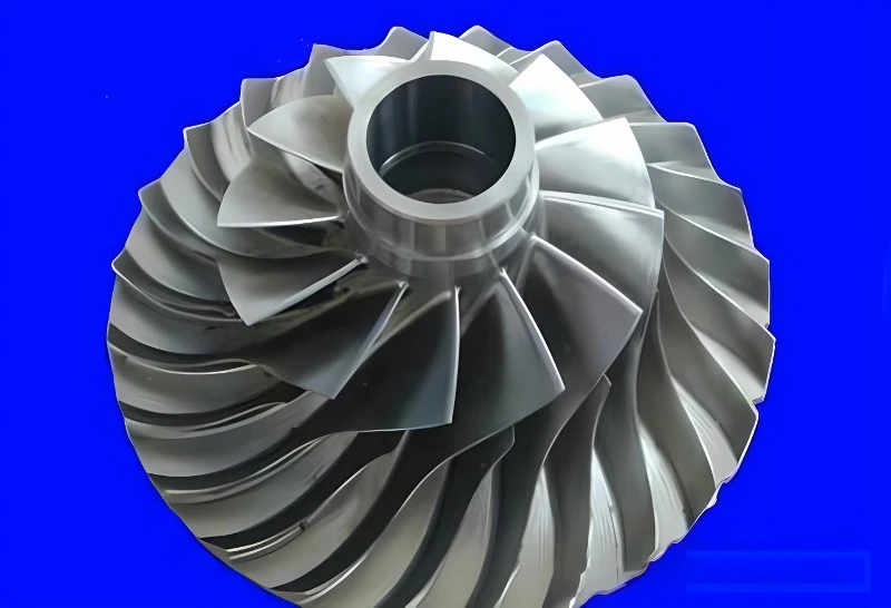
The tool should be changed when it has reached about 2/3 of its maximum lifespan. For example, if the tool shows severe wear after 60 minutes of use, it should be changed at 40 minutes during the next machining process. Developing a habit of regularly scheduled tool changes is essential.
19. Can a severely worn tool continue to be used?
After severe wear, the cutting force can increase up to three times the normal level. Cutting force has a significant impact on the lifespan of the spindle motor, with the motor's lifespan inversely proportional to the cube of the force. For instance, machining for 10 minutes with the cutting force increased three times is equivalent to using the spindle for 270 minutes under normal conditions (10 * 3^3 = 270).
20. How to determine the tool's protrusion length during rough machining?
The shorter the tool protrusion length, the better. However, if it is too short, frequent adjustments will be needed, affecting efficiency. The guideline is: a φ3 diameter tool rod can extend 5mm, a φ4 diameter tool rod can extend 7mm, and a φ6 diameter tool rod can extend 10mm for normal machining. When setting the tool, try to stay within these values. If the tool's length exceeds these values, control the cutting depth during tool wear. This requires practice to master.
21. How to handle sudden tool breakage during machining?
1) Stop machining and check the current machining sequence number.
2) Check the breakage point for any remaining tool body, and remove it if present.
3) Analyze the cause of the tool breakage, which is crucial. The breakage typically occurs due to a sudden increase in cutting force, which could be caused by a path issue, excessive tool vibration, hard spots in the material, or incorrect spindle speed.
4) After analysis, replace the tool and resume machining. If the path is not changed, start machining one sequence earlier, reduce the feed speed because the breakage point is heavily hardened, and allow the tool to break in.
22. How to adjust machining parameters when rough machining is not going well?
If tool life cannot be ensured at a reasonable spindle speed, adjust the parameters by reducing the cutting depth first, then the feed speed, and finally the side feed amount. Note that reducing the cutting depth has limits-too shallow a depth results in excessive layers, which theoretically improves cutting efficiency but may lower actual machining efficiency due to other factors. In such cases, switching to a smaller tool might be more efficient, with a minimum cutting depth generally not less than 0.1mm.