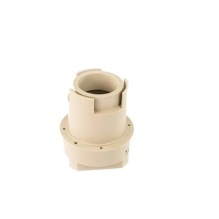
Valve train control equipment and technical realization elements for fixing return spring equipment
Jan 08, 2022
Leave a message
Technical realization elements:
3. The purpose of the present invention is to construct the valve mechanism control device more simply, at lower cost and more stably. The return spring device should be simpler to construct and quicker and more reliable to fix.
4. At least one of the objectives is achieved by the valve train control device having the characteristics of the present invention. As a result, the return spring device can be fixed more simply and at a lower cost. The number of components and installation costs can be reduced.
5. The valve mechanism control equipment can be installed in the vehicle. The internal combustion engine may be a reciprocating piston engine. The valve may be a scavenging valve, especially an intake valve or an exhaust valve.
6. The first maximum valve lift can be greater than the second maximum valve lift. The first maximum valve lift can be full lift and the second maximum valve lift can be zero lift. As a result, selective cylinder shut-off of the internal combustion engine can be achieved. The first maximum valve lift can be a full lift and the second maximum valve lift can be a subsequent lift that follows the full lift in time and is less than the full lift in absolute value.
7. The switching device can have a roller traction rod. The switching device can have an axially movable switching bolt for switching between the first and second switching positions. The thrust element can switch the switching device via the spring element. The spring element can elastically transmit the operating movement to the switching device. The spring element can be directly coupled to the switching bolt. The spring element may be a leaf spring and/or a spring plate. The spring element can be fixedly connected to the thrust element, in particular in a form-fitting, force-fitting and/or material-fitting manner.
8. The first switching position can be a first position with respect to the operating direction and the second switching position can be a position axially shifted with respect to the operating direction. The operating direction can extend in the axial direction.
9. The thrust element can be an axially movable thrust bar. The thrust element can extend parallel to the camshaft. The thrust element can be constructed from a plate.
10. The thrust element can be operated by operating elements, such as actuators. The actuator can be a linear actuator. Operand
Pieces can cause operations in the axial direction. The operating element can be fastened to the internal combustion engine, in particular connected to the cylinder head.
11. The return spring device can cause a return force in the direction of the first switching position. The return spring may be arranged on the side of the thrust element that is opposite to the operating element in the axial direction. The return spring device can also be arranged to coincide with the thrust element in the axial direction.
12. The return spring can be constructed as a coil spring. The return spring can directly abut on the first support element and the second support element. The helical spring can be arranged at least in sections to coincide axially with the first and/or second support element.
13. The second support element can be formed as a guide pin. The guide bolt can be arranged in the return spring. The second support element may have a greater length in the axial direction than the first support element.
14. The first support element may be configured as a guide sleeve that can move axially on the guide pin. The guide sleeve may be a spring sleeve.
15. The inner diameter of the inner edge may be smaller than the maximum outer diameter of the first support element in the area facing away from the return spring and adjacent to the outer circumferential recess. The outer circumferential recess may be an undercut. The axial width of the outer circumferential recess may be greater than or equal to the material thickness of the inner edge.
16. The inner edge may include a protrusion projecting radially inward. The inner edge can also be uniformly cylindrical.
17. In a preferred embodiment of the present invention, the inner edge is fixed to the outer circumferential recess via a snap connection. As a result, the installation of the return spring device can also be performed more simply and faster. The inner edge can be elastically deformed.
18. In a specific embodiment of the present invention, the outer circumferential recess is formed as an annular groove. As a result, the first support element can be constructed at a lower cost.
19. In another specific embodiment of the present invention, the first support element has an abutment area, which abuts axially on the thrust element. The outer circumference of the abutment area is preferably larger than the diameter of the inner edge. The contact area can be formed as a flange. The contact area can be arranged to rest on the thrust element on one side and to rest on the return spring on the other side.
20. In a specific embodiment of the present invention, the abutment area directly adjoins the outer circumferential recess axially. The abutment area can be arranged axially between the outer circumferential recess and the return spring.
21. In another specific embodiment of the invention, the abutment area is formed as a diameter widening. The outer diameter of the abutment area can be larger than the diameter of the return spring.
22. In a preferred embodiment of the invention, the first support element surrounds the second support element. The second support element can also surround the first support element. The first support element can be formed as a spring bolt and the second support element can be formed as a spring sleeve.
23. In a preferred embodiment of the present invention, the first supporting element has a through opening, and the second supporting element is inserted through the through opening. The second support element can also have a through opening in which the first support element is inserted.
24. In a preferred embodiment of the present invention, the second support element has an abutment area for limiting the maximum movement between the first and second support elements in at least one direction. The contact area can be formed in one piece on the second support element as a diameter widening. The contact area can also be formed on a fixing ring fixed to the second support element.
25. In order to achieve at least one of the objectives given above, in addition, a method for fixing a return spring device of a valve train control device having at least one of the above-mentioned features is proposed. In the method, the first support element is inserted from one side through the through opening of the thrust element until its inner edge is directly engaged with the outer circumferential recess of the first support element in a form-fitting manner at least in sections. As a result, it is possible to simplify the installation of the valve train control device.
26. Other advantages and advantageous design solutions of the present invention are drawn from the description of the drawings and the drawings.
Please contact us at zhang@pride-cnc.com