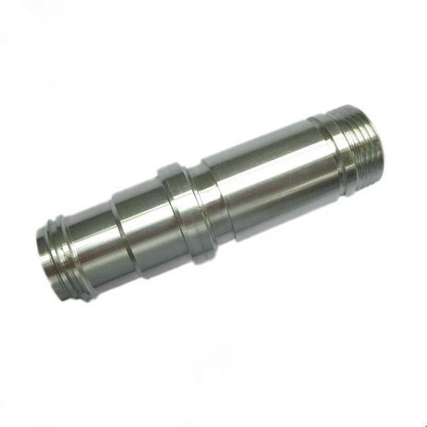
Technical realization elements of safety tension lock with protective function for rail transit
Jan 17, 2022
Leave a message
Technical implementation elements:
4. The purpose of the present invention is to provide a safety tension lock with a protective function for rail transit, so as to solve the problem of poor protective effect of the device proposed in the above-mentioned background technology.
5. In order to achieve the above purpose, the utility model provides the following technical solutions: a safety tension lock with a protective function for rail transit, comprising a main body lock cylinder, a panel and a rotating shaft, and the bottom end of the main body lock cylinder is installed with a Panel, the surface of the main body lock cylinder is provided with a fixing structure, the middle of the panel is provided with a rotating shaft for support, the top end of the main body lock cylinder is provided with a disassembly structure, and the surface of the disassembly structure is provided with a protective structure, so The protective structure includes a protective coating, a primer layer, a groove and a special-shaped groove, the grooves are all arranged on the surface of the disassembly structure, the main body lock cylinder and the panel, and special-shaped grooves are installed on both sides of the groove. A primer layer is installed on the top of the groove, and a protective coating is installed on the top of the primer layer.
6. Preferably, the fixing structure includes a threaded strip, a nut, a counter-grip and a washer, the threaded strip is arranged on the surface of the main body lock cylinder, a nut is installed on the surface of the threaded strip, and the nut is The bottom end is provided with an opposing tooth piece, and the bottom end of the opposite tooth piece is provided with a gasket.
7. Preferably, the nut and the threaded rod are connected in a threaded manner, and the outer diameter of the nut is larger than the outer diameter of the threaded rod.
8. Preferably, several groups of the grooves are arranged on the surface of the main body lock cylinder, the panel and the disassembly structure, and the several groups of grooves are arranged at equal intervals on the surface of the main body lock cylinder, the panel and the disassembly structure.
9. Preferably, the dismantling structure comprises a tab, a fixing screw and a screw groove, the screw groove is provided inside the main body lock cylinder, the top of the screw groove is provided with a tab, and the top of the tab is provided with a tab. Fixed screw.
10. Preferably, the fixing screw and the screw groove are threadedly connected, and the inner diameter of the groove body on the surface of the tab is larger than the outer diameter of the fixing screw.
11. Compared with the prior art, the beneficial effects of the present utility model are: the safety tension lock with a protective function for rail transit has a reasonable structure and has the following advantages:
12. (1) Coat the primer layer and top protective coating on the surface of the main body lock cylinder, the panel and the dismantling structure respectively.
At the same time, the external objects and the air are isolated to prevent the external air from contacting the main body lock cylinder, panel and disassembly structure to cause corrosion and oxidation, so that the main body lock cylinder and the disassembly structure will not be rusted and stuck. Therefore, the protection function of the device is realized, and the service life of the device is improved;
13. (2) By turning the nut, the nut is threaded on the surface of the threaded strip, and at the same time, the nut will squeeze the opposite card teeth, and at the same time the opposite card teeth will be in contact with the gasket. When the plate is squeezed between the washer and the nut, it uses its own characteristics to fix the main body lock cylinder to avoid the phenomenon of the main body lock cylinder shaking after installation, thus realizing the stable function of the device and improving the device. practicality;
14. (3) By rotating the fixing screw, at the same time, the fixing screw is detached from the inside of the screw groove through the thread. When the fixing screw is completely separated from the inside of the screw groove, the tab on the surface of the fixing screw can be removed, and then the tab can be removed. Replacement and disassembly, thereby realizing the disassembly function of the device and improving the convenience of the device.
Please contact us at zhang@pride-cnc.com