Talk about spring chucks in a simple way 2
Mar 16, 2021
Leave a message
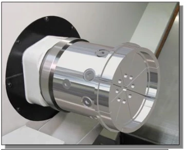
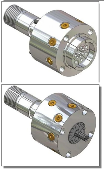
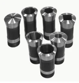
This is a variety of styles of spring chucks, including special-shaped chucks, disc chucks (at the expense of through-hole performance, which can clamp some disc parts) corn tooth chucks and so on.
According to the locking method, it can be divided into pushing and tightening. ) ^1 _ `
The structure in the figure below is a tension collet structure with a collet chuck adapter for a standard lathe spindle .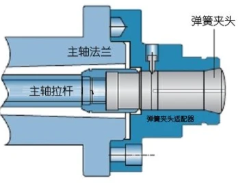
The figure below shows a push-type spring chuck structure: 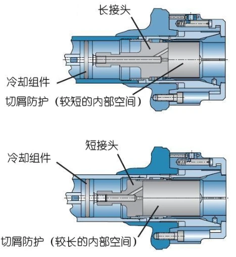
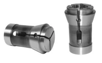
is divided according to the clamping effect, it can be divided into ordinary collet chuck and fixed-length collet chuck |
As someone said before, the length accuracy of the collet chuck of the ordinary structure will be lost, which will seriously affect the length accuracy of the workpiece in the precision machining. Therefore, a fixed-length spring chuck was developed a long time ago
. The figure below is a fixed-length spring chuck with a structure, which can realize the stable clamping of small workpieces without loss of length accuracy. Clamping is mainly carried out by pulling force.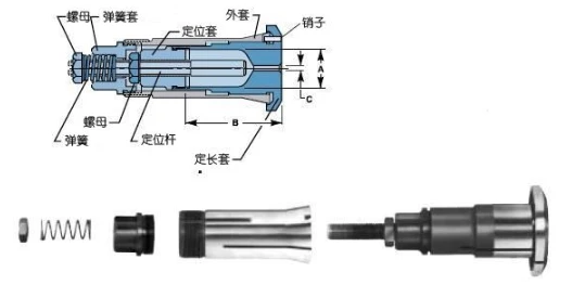
In fact, a pull-clamping collet chuck is divided into two parts. The tapered part can be moved backwards separately, thereby exerting a clamping force toward the axis, while the holding part is fixed and does not follow the cone. movement.
The picture below is another fixed-length spring chuck. Clamping mainly depends on thrust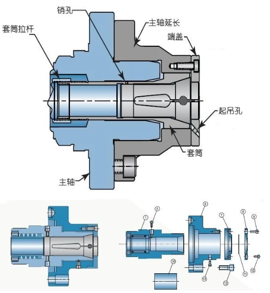
Can also be divided, with a fixed cutter and a workpiece clamping chuck with a chuck
whichappreciated had a relatively good, for example, a turret designed for mounting a tool chuck ER series, see below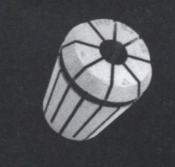
If it is divided according to whether there is a center passing capacity, it can be divided into through-hole spring chucks and non-through-hole chucks. "
Generally speaking, through-hole collet chucks cannot clamp parts that are too thick, but long rod parts can be clamped. Instead of through-hole spring chucks, parts with larger diameters can be clamped (of course, it is not as good as The chuck adapts to a large diameter range), but this type of chuck cannot hold a long rod and cannot extend the workpiece into the spindle through hole.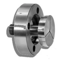
This chuck can be machined into the desired size with a turning tool by itself to form a stepped chuck for clamping parts with larger diameters.
But he does not have the ability to pass the main shaft.
According to the clamping shape, it can be divided into standard round collet chuck and special-shaped chuck .
As the name implies, the round collet chuck can only clamp parts or bars whose contact surface is a circular reference. The special-shaped spring chuck is not a standard product, but a spring chuck customized according to the shape of a specific processed part, which has no versatility.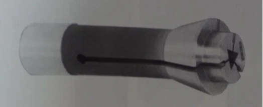
This is a spring chuck that holds a triangle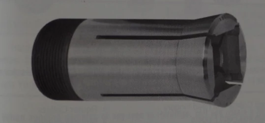
This is a square spring chuck 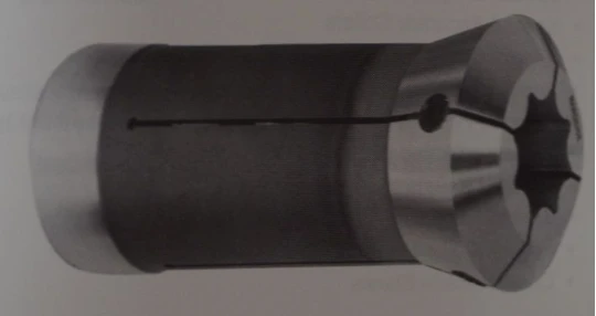
This guy is even more versatile, and can hold polygons, quadrilaterals, triangles, and so on. Of course, you can temporarily clamp the circular shape.
If you want to divide it according to the structure of the chuck, it should be divided into an integral chuck and a split chuck.
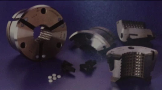
Yes, the spring chuck can also be made into a multi-part type. Connect with flexible materials such as rubber.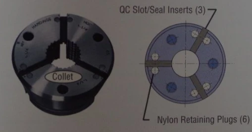
The following figure shows the schematic diagram of use: 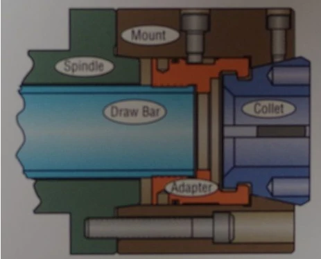
The use of
collet chuck In the process of using the collet chuck, if it is used with high precision, it will generally be bored first, so that the accuracy of the chuck is the accuracy of the spindle. For the spring chuck after the front end is quenched, as long as the use is reasonable, the life factor does not need to be considered at all. There are also corn tooth type and special-shaped spring chucks. Those precisions are determined by the manufacturing precision of the chucks.
The clamping force is the force exerted by the machine tool on the workpiece via the collet. The collet chuck can not only be used to position and clamp the turned workpiece, but also can be used to position and clamp the tool, grinding and milling workpiece, or many other occasions. The external thread of the pull rod of the machine tool spindle is connected to the internal thread of the rear end of the spring chuck to be tightened to generate axial tension. Then, the conical surface called the locking angle at the front end of the machine tool spindle converts the axial tension into a clamping force perpendicular to the center of the collet. Not only that, the clamping force can also be expanded by the locking angle. According to calculations, the clamping force of the collet chuck can be expanded 3-4 times according to different locking angles.
The collet chuck is a simple process device, but there are many main factors that affect the clamping force. An understanding of the basic principles can help the workpiece (or tool) to be clamped correctly and to find faults quickly. The following introduces several main factors affecting the clamping force and summarized use experience:
1. Axial force. The pull rod exerts an axial tension on the collet. In the use of the spring chuck, the axial force can be applied in different ways, but the principle of action is basically the same. Therefore, a large axial tension will produce a large clamping force, and vice versa. Generally, the axial tension of the tie rod can be adjusted on the CNC machine tool.
2. In the use of the spring chuck, the locking angle of the chuck will determine the radial clamping force that the spring chuck can provide under the same axial tension, usually by the machine tool manufacturer and the spring clamp The head manufacturer decides. The choice of locking angle should be based on economy and reliability, according to the type of machine tool (such as lathe, etc.), use conditions (dynamic and static) and use (workpiece and tool) to determine.
3. The friction between the workpiece (or tool) and the collet will directly affect the firmness of the clamping (but does not affect the clamping force). The greater the friction, the firmer the workpiece will be clamped, and vice versa. In order to overcome the relative rotation or axial movement between the spring chuck and the workpiece (or tool), various measures can be taken during the manufacturing process of the spring chuck to increase the friction force. For example, the inner hole of the spring chuck is deliberately made Sawtooth shape or immersion of cemented carbide micro-crystal grains on the clamping surface, etc.
4. The friction between the conical surface of the spindle and the collet at the locking angle. The friction force also directly affects the clamping force of the collet on the workpiece. If the friction force is too small, the clamping force will be insufficient, and the relative rotation of the workpiece will be generated; and too large clamping force will accelerate the wear of the collet.
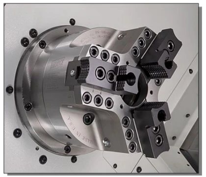
In actual use, the collet should be loosened frequently to replace the workpiece, such as on a turning machining center. It can be used to spray a layer of lubricant on the surface of the inner hole of the spring chuck when it is loosened. If possible, it is better to use coolant to lubricate, so that it can wash the debris on the spring chuck and provide good lubrication effect. . Applying grease regularly to the locking angle of the collet can reduce long-term wear and increase clamping force. Other materials with better lubricating effect can also be used, including high-quality grease or wax-based materials with EP (limiting pressure) characteristics. 5. Reasonable selection of the clamping diameter of the spring chuck can ensure that the spring chuck produces the greatest clamping force on the workpiece, and achieves the best clamping state, so as to ensure the high quality and high precision of machining. If the diameter of the inner hole of the collet chuck is too large, the workpiece is only clamped by the opening of the collet when the chuck is closed, which is likely to cause a geometric mismatch between the outer circle of the workpiece and the inner hole of the collet. Therefore, the clamping force is reduced. If the diameter of the inner hole of the collet chuck is too small, only the inside of the inner hole of the chuck contacts the workpiece when the chuck is closed. Although the clamping force is increased, it will cause the chuck and the workpiece to have different axes. A collet chuck of a specification size can only clamp and position the workpiece of the corresponding diameter size. A company that specializes in spring chucks recommends that the applicable range of spring chucks is ±0.0254mm. "A Brief Talk on Spring Chuck " (off-topic) Nowadays, high-speed chucks already have a claw balance device, and the claw force will not drop too much as the rotation speed increases. Therefore, many high-speed chucks can reach applications with more than 4,000 revolutions.
The following figure shows a high-speed chuck structure. His counterweight part can offset the centrifugal force of the claws.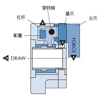
"In-depth and simple talk about collet chucks" (4)
Continue to come back to talk about collet chucks. As for the classification, performance, and use of collet chucks, I believe many people have a certain understanding, and more people estimate that it is better than me. To understand more, I
will introduce some chucks with special functions and special applications from the fourth part.
First introduce a chuck used for the clamping and processing of
thin-walled ring parts. When the thin-walled ring parts are processed and clamped, the deformation of the parts is the most troublesome. The deformation we are talking about here is not simply the deformation by the clamping force. Deformation is easy to solve, and it can be solved with enveloping or inward expansion clamping. The problem we want to solve is that although thin-walled ring parts are processed in accordance with the constraints of the fixture, they turn into a circle with small deformation to complete the processing, but when the part is removed, the elastic part will maintain the shape (roundness) before processing. The initial shape with a large error), which causes a large error in the measurement of the thin-walled ring part on the equipment and when it is taken off the measurement, which causes the roundness of the processed part to be unqualified.
A company (forgive me for not telling which company it is) has developed a hydraulic chuck in response to this situation. This chuck is divided into many flaps, and each flap can be changed separately, which is guaranteed by the hydraulic system. The clamping force of each petal is the same, so that the clamping of the part can be completed while keeping the original shape of the thin-walled ring part unchanged. The size processed in this way will not change after being removed from the machine tool.
Don’t gossip, see the picture below, I don’t understand the specific internal structure