

Overview of CNC Wire Cutting
Apr 07, 2021
Leave a message
Overview of CNC Wire Cutting
Wire cutting processing - belongs to pulse electric discharge machining, which requires good electrical conductivity of the processed parts.
1. The composition of the fast-moving wire cutting machine tool
It is mainly composed of host, machine tool electrical box, working fluid tank, adaptive pulse power supply and numerical control system, as shown in Figure 1 .
Figure 1 HCKX250A CNC fast-moving wire-cutting machine tool
2. Machining principle of wire cutting machine
(1) Wire cutting - short for CNC wire cutting.
(2) Working principle: Use the moving metal wire as the tool electrode, and pass the pulse current between the metal wire and the workpiece, and use the corrosive effect of the pulse discharge to cut the workpiece.
(3) Because it uses wire electrodes, it can only be used for contour cutting.
(4) The working principle is shown in Figure 2 .
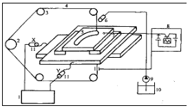
Figure 2 Processing principle of wire cutting machine
1--Numerical control device, 2--Wire storage, 3--Guide wheel, 4--electrode wire, 5--workpiece, 6-nozzle
7--Insulation plate 8--Pulse generator 9--Hydraulic pump 10--Water tank 11--Control stepping motor
(5) When the gap between the workpiece and the wire electrode is sufficient to be broken down by the pulse voltage, a spark discharge is generated between the two to cut the workpiece.
(6) The stepping motor 11 is controlled by the instruction issued by the numerical control device 1 , and the X and Y pallets are driven to move, and the workpiece with any curve contour can be processed.
3. Classification of wire cutting machine tools
(1) According to the different control methods, wire EDM machine tools are divided into: electric profile wire cutting machine tools; photoelectric tracking wire cutting machine tools; digital control wire cutting machine tools.
(2) According to the different ways of wire electrode wire, CNC wire cutting machine tools are divided into: fast wire wire cutting machine tools; slow wire wire cutting machine tools.
1) Fast-moving wire cutting machine
① The wire electrode runs faster (300-700m / min) .
②It can run back and forth in both directions, that is, the wire electrode can be used repeatedly until the wire electrode is worn to a certain degree or the wire is broken.
③The commonly used wire electrode is: molybdenum wire ( Φ 0.1 ~ Φ 0.2mm) .
④Working liquid is usually: emulsion or saponification liquid.
⑤ Due to the loss of the electrode wire and the influence of the commutation during the movement of the electrode wire, the machining accuracy is worse than that of the slow wire, and the surface roughness is higher;
⑥Dimensional accuracy: 0.015 ~ 0.02mm ;
⑦Surface roughness R ɑ : 1 . 25 ~ 2.5 μ m .
⑧The highest general dimensional accuracy can reach: 0 . 01mm , the surface roughness R ɑ is: 0.63 ~ 1.25 μ m .
2) Slow walking wire cutting machine
①The running speed of the wire electrode is relatively low (0.5 ~ 15m/min) .
②The wire electrode can only move in one direction and cannot be reused, which can avoid the influence of electrode wear on the machining accuracy.
③Wire electrodes include: red copper, brass, tungsten, molybdenum and various alloys, and the diameter is generally 0.1 ~ 0.35mm .
④Working fluid: deionized water, kerosene.
⑤Dimensional accuracy: ± 0.001mm
⑥ Surface roughness: Ry0.3 [mu] m .
4. Wire cutting process indicators
Commonly used process indicators are: cutting speed, processing accuracy and surface roughness.
(1 ) Cutting speed
1) Wire cutting is the processing of cutting seams on the workpiece.
2) The cutting speed ( or processing speed ) indicates:
①The effective area cut by the electrode wire center in unit time (mm 2 /min) ;
②The feed speed (mm / min) adds the thickness of the wire cutting.
(2) Machining accuracy
Machining accuracy includes: the shape accuracy and position accuracy of the processed workpiece.
1) Shape accuracy
① The shape accuracy of the workpiece to be processed refers to the plane accuracy ( ie, dimensional accuracy ) of the processed shape viewed from the XY plane , and the Z- direction perpendicularity of the processed surface .
②Improve shape accuracy: The linearity of the cutting surface is required to be small. That is: the surface to be processed should be uniform and smooth, and the verticality should be small.
③The workpieces processed by slow-moving wire cutting are mostly in the shape of a waist drum, that is, the middle of the workpiece is recessed.
④The opposite is true for fast-moving wire, usually the middle part of the workpiece protrudes.
2) Position accuracy
①Position accuracy - refers to the relative position deviation between the cut contours.
②The determinants of position accuracy:
a. The accuracy of the machine tool itself, that is, the mechanical accuracy and control accuracy of the machine tool;
b. The positioning method selected during operation.
3 ) Machining surface roughness
①Surface roughness - refers to the microscopic unevenness of the contour surface after processing.
②The parameters indicating roughness mainly include: R ɑ , R z , R y .
③The surface roughness of slow-moving wire cutting is expressed by the following formula: R y = k z t k 0.38 I p 0.34
In the formula: κ z is a constant; t k is the pulse width ( μ s) ; I p is the pulse peak current (A) .
5. Factors affecting the processing technology index
It can be divided into the influence of electricity and non-electricity factors.
(1 ) The influence of electrical parameters on processing technology indicators
Electrical parameters - refers to the parameters of the pulse power supply, including pulse peak value, pulse width, pulse frequency and power supply voltage.
1) The impact of pulse peak current on processing technology indicators
When other parameters remain unchanged, the increase of the pulse peak current will increase the energy of a single pulse discharge, and the processing current will also increase accordingly. The wire cutting speed will increase significantly and the surface roughness will become worse.
2) The impact of pulse width on processing technology indicators
① Under the condition that the processing current remains unchanged, the pulse width and pulse rest time are changed in a certain proportion.
② When the pulse width increases, the cutting speed will increase , but after the pulse width increases to a certain value, the processing speed will no longer increase with the increase of the pulse.
③ cutting line usually not more than a pulse width of 50 [mu] S .
④ If the pulse width is increased, the surface roughness will increase .
3) The influence of pulse frequency on processing technology indicators
①Under the condition of a certain single pulse energy, increase the number of pulse discharges, that is, increase the pulse frequency, and the processing speed will increase.
②Theoretically, if the energy of a single pulse remains unchanged, the roughness of the processed surface will also remain unchanged.
③In fact, for fast-moving wire cutting, when the pulse frequency is increased, the processing current will increase, causing obvious differences in the commutation cutting stripes, and the surface roughness of the cutting workpiece will become worse.
4) The influence of power supply voltage on processing parameters
①In the condition that the peak current and processing current remain unchanged, increasing the power supply voltage can significantly increase the cutting speed, but it has little effect on the surface roughness.
②Under the conditions of difficult chip removal, low energy and small roughness, and when cutting high-impedance and high-melting materials, the increase of the power supply voltage will improve the stability of the processing, and the cutting speed and the quality of the processed surface will be improved.
(2) The influence of non-electrical parameters on processing technology indicators
1) Wire speed
① Impact on cutting speed: It is mainly achieved by changing chip removal conditions .
②Improving the wire speed is beneficial: the wire electrode brings the working fluid into the discharge gap of the workpiece with a larger thickness; the discharge of the electro-corrosion product makes the processing stable and increases the processing speed.
③Excessively high wire speed: it will cause increased mechanical vibration, reduced processing accuracy, and increased surface roughness, and it is easy to cause wire breakage.
④For fast-moving wire cutting, the effect of the commutation cutting stripes on the surface roughness caused by the change of the wire electrode speed should be considered.
2) The influence of electrode wire tension on processing technology indicators
① Increasing the tension of the electrode wire can reduce the vibration of the wire during the processing, thereby improving the processing accuracy and cutting speed.
②If the tension of the wire is increased too much, it will cause frequent wire breakage and affect the processing speed.
③The fluctuation of electrode wire tension has a great influence on processing stability and processing quality. The use of constant tension device can reduce the fluctuation of wire tension .
3) The influence of the electrode wire on the processing technology index
① Including two aspects of silk material and silk thickness
②Wire electrode material : brass and copper wire are mostly used as electrode material for slow-moving wire cutting, and molybdenum wire and tungsten-molybdenum alloy are mostly used as electrode material for fast-moving wire cutting.
③The thickness of the wire: increasing the wire radius can increase the allowable pulse current value of the electrode wire and increase the processing speed, but at the same time, the roughness of the processed surface will increase. Generally, thick electrode wires are used to cut thick workpieces; thin electrode wires are used to cut workpieces with high roughness requirements.
4) The influence of workpiece thickness on machining process indicators
①When cutting thin workpieces
The working fluid is easy to enter and fill the discharge gap, which is conducive to chip removal and elimination of positive and negative ions in the working fluid during the electrolyte process.
However, if the workpiece is too thin, it is easy to cause the electrode wire to shake, which is not conducive to processing accuracy and surface roughness.
②When cutting thick workpieces
The working fluid is difficult to enter and fill the discharge gap, so the processing stability is poor, but because the electrode wire is not easy to shake, the processing accuracy and surface roughness are better.
5) The influence of working fluid on processing technology indicators
①The role of working fluid: dielectric, cooling, chip removal, etc.
②Influence on processing speed and processing quality:
The workpiece processed with kerosene is dark gray;
The workpiece processed with deionized water is gray;
The workpiece processed by the emulsion is silvery white.
③The influence of the resistivity of the working fluid on the processing speed:
The working fluid devices of fast-moving wire cutting machine tools generally do not have purification facilities, and the working fluid should not be used for too long;
Slow wire cutting uses deionized water, so the ion exchange resin should be replaced regularly.
6. The processing form of wire cutting
Wire cutting processing can be divided into plane processing, taper processing and secondary cutting processing.
(1) Plane processing
Plane processing - refers to the wire electrode is always strictly vertical during the machining process, and the wire electrode only moves in the X and Y directions to process the two-dimensional planar shape.
(2) Taper processing
Taper processing - refers to the three-dimensional processing of upper and lower abnormal shapes through the control of the X , Y , U , and V axes during the processing.
It is necessary to specify the value of the variable when performing taper processing:
A : Define the taper to be processed, Z1 : Program surface height
Z2 : the height of the processing speed display surface, Z3 : the distance from the upper guide nozzle to the upper surface of the worktable ( equal to Δ Z3+S+Z5)
Δ Z3 : used to determine the parameters of Z3 , which are automatically determined by the system after the equipment is installed and debugged
S : The gap between the upper guide nozzle and the upper surface of the workpiece , measured with a feeler gauge after the workpiece is clamped , generally 0.1 ~ 0.2mm is appropriate.
Z4 : The distance from the lower guide nozzle to the upper surface of the worktable. This parameter is automatically determined by the system after the equipment is installed and debugged; Z5 : The height of the non-program surface corresponding to the program surface.
Figure 3 Taper processing device
1- Wire recovery 2- Wire lower guide 3- Wire upper guide 4- Wire supply 5-V axis driver
6-U- axis driver 7-Y- axis driver 8-X- axis driver 9- CNC paper tape
Figure 4 The meaning of taper processing parameters
A : Define the taper to be processed; Z1 : Program surface height; Z2 : Processing speed display surface height;
Z3 : the distance from the upper guide nozzle to the upper surface of the worktable ( equal to Δ Z3+S+Z5) ; Z5 : the height of the non-program surface corresponding to the program surface;
Δ Z3 : Used to determine the parameters of Z3 , which are automatically determined by the system; S : The gap between the upper guide nozzle and the upper surface of the workpiece, generally 0.1 ~ 0.2mm is appropriate.
Figure 5 Definition of the sign of the taper A value
Taper A sign of the value of the filament defined radius offset method used (G41 , G42) related
(3) Secondary cutting processing
1) Secondary cutting - pre-finishing allowance left for a first cutting, and then for the remaining finishing allowance, the processing conditions to finishing conditions, reduce the offset segment, then Cutting process.
2) Generally, it can be divided into 1 to 5 cuts, which is called the secondary cutting processing method.
The secondary cutting process has the following three purposes:
①The protruding part left at the initial joint during the first cutting can be removed.
②Improve the surface roughness. Gradually change the electrical conditions during each cut, reduce the energy of a single pulse, and improve the surface roughness of the machined.
③Improve dimensional accuracy.
Heat-treated materials will generate internal stress, which is in a stable internal state, but after being processed by wire-cut electrical discharge machining, this stable state will be destroyed, releasing internal stress and causing deformation.
For the rough-machined workpiece, performing 1 to 4 times of finishing can improve the surface roughness and correct the dimensional accuracy.