

How to correctly process the thread of CNC lathe(1)
Jul 08, 2020
Leave a message
How to correctly handle the processing threads of CNC lathes On CNC lathes, four standard threads can be turned: metric, foot, modulus, and diameter control. No matter which thread is turned, the lathe spindle and CNC blade need to maintain a strict motion relationship with each other: namely For each revolution of the spindle (that is, the workpiece rotates once), the CNC blade should be moved by a pitch (of the workpiece) symmetrically. The following is based on the analysis of various types of threads, to enhance the grasp of various types of threads, to facilitate the stronger processing of various types of threads.
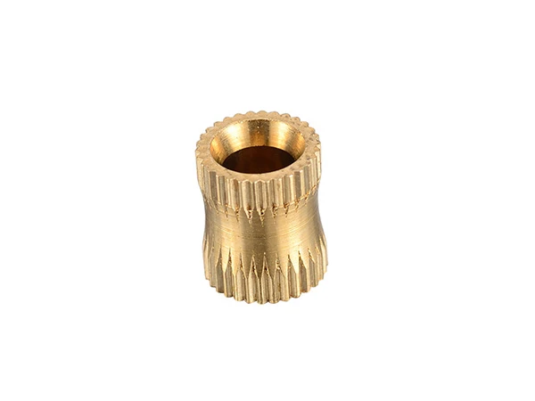
Auto parts processing customization
1. Specification analysis of common thread
CNC lathe processing has many specifications for ordinary threads. The calculation and analysis of specifications required for ordinary thread processing mainly includes the following two levels:
1. Diameter of steel before threading
Following the shrinkage of the thread profile, the workpiece diameter before threading is D/D-0.1P, that is, the major diameter of the thread minus 0.1 pitch, which is usually 0.1 to 0.5 smaller than the major diameter of the thread according to the material deformation potential.
2. Thread processing feed
The increase of the amount of thread can refer to the thread bottom diameter, that is, the last part of the thread cutter.
The small diameter of the thread is: large diameter-2 times the tooth height; tooth height = 0.54P (P is the pitch)
The cutting amount of thread processing should be continuously reduced. The actual cutting amount is selected according to the CNC blade and the working material.
2. Selection and setting of general thread CNC blades
If the turning tool is installed too high or too low or too high, when the knife is eaten to a certain thickness, the back face of the milling cutter bears against the steel part, increasing sliding friction, and even bending the workpiece up, resulting in a bite. Cutting is difficult to discharge, the direction of the axial force of the turning tool is the center of the workpiece, and the gap between the lead screw and the nut is too large, causing the thickness of the knife to continue to automatically deepen, and then the workpiece is extended to show the bite. At this time, the aspect ratio of the turning tool should be adjusted immediately so that the cutting edge is equidistant from the center line of the workpiece (the tool can be adjusted by the center of the tailstock). During boring and semi-finishing, the edge of the blade is 1% D higher than the center of the workpiece (D represents the aperture of the workpiece to be processed).
Unstable clamping of the workpiece The rigidity of the workpiece itself cannot bear the cutting force during cutting, so that excessive deflection is formed, and the center height of the turning tool and the workpiece is changed (the workpiece is raised), resulting in a sudden increase in cutting thickness and a bite. At this time, the workpiece should be clamped firmly, and the tailstock top can be applied to improve the rigidity of the workpiece.
General thread setting methods include trial cutting method tool setting and tool setting instrument automatic tool setting, which can be used to directly test the tool setting with a CNC blade. You can also use G50 to set the workpiece zero point, and use the workpiece shift to set the workpiece zero point for tool setting. The standard for threading tool setting is not very high, especially the Z direction tool setting is not strictly limited, and can be determined according to the programming processing standard.