

Formula for Follow-up Grinding
Jul 28, 2020
Leave a message
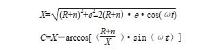
X-grinding wheel frame transverse slide moving shaft; C-head and tail seat workpiece clamping rotary shaft.
The use of follow-up grinding method is a more advanced processing method, but it has higher requirements for equipment, especially the relationship between hardware and software more closely. The follow-up grinding method actually involves the relationship between the rotation position of the crankshaft and the straight motion of the grinding wheel frame, and the key is:
(1) C 1, C 2 and X 1 must remain in sync. Is the head c 1 and tail seat C 2 clamped crankshaft two ends, eccentric to the spindle neck of the link neck center line, around the C 1, C 2 rotation axis of the motion trajectory, and X 1 shaft sand wheel frame horizontal slide moving in a straight distance relationship, always to make the outer diameter of the rod neck at any angle of 360 degrees to maintain the outer circle of the grinding wheel to maintain a cut position.
(2) The precision of the mechanical transmission chain, the precision of the grating feedback system, and the accuracy of the on-line measurement system.
(3) The development of follow-up grinding application software reasonable and practical.
The above problems will directly affect the accuracy of grinding processing, for this reason, machine tool manufacturers in x grinding wheel frame horizontal slide moving shaft, designed to be rigid, good vibration absorption, high precision static closed rail system. The X-axis drive uses a straight-line motor that locates non-mechanical drives with good repeatability and small transmission clearance. X-axis positioning is precise with a straight grating ruler.
Head C 1 and tail seat C 2 use water-cooled torque motors to drive the workpiece directly, and the high-resolution round grating eliminates the gap between mechanical drives, preventing the appearance of up and down dead points when rotating the head and tail seating during grinding, and maintaining synchronization and constant line speed grinding. These measures can theoretically ensure that the roundness of the grinding rod neck reaches the requirements of 0.005mm and surface roughness. At the same time, in order to improve the grinding wheel spindle speed to improve the grinding wheel speed, ordinary grinding circumference (line) speed of up to 45m/s, the motor spindle drive power reached 78kW, the structure of the grinding wheel spindle box is also optimized. Change the original barrel-shaped shaft tile support to a high-precision, maintenance-free ceramic ball bearing structure. In order to improve the accuracy of the grinding wheel spindle, an automatic balance system with grinding wheel (manufactured by MARPOSS, Italy) is also formulated, integrated with the grinding wheel spindle, and has an ultrasonic gap control system (noise control) as a protective device to prevent grinding wheel collision workpieces. In order to make the workpiece processing on the machine to find the right convenience, but also designed with the crankshaft anti-sagging compensation function, the sagging of the crankshaft can be installed on the grinding wheel head frame pre-set center of the measuring head system, to detect the actual position of the crankshaft, and the original set-up center after comparison, through the numerical control system for the numerical control center frame control compensation.