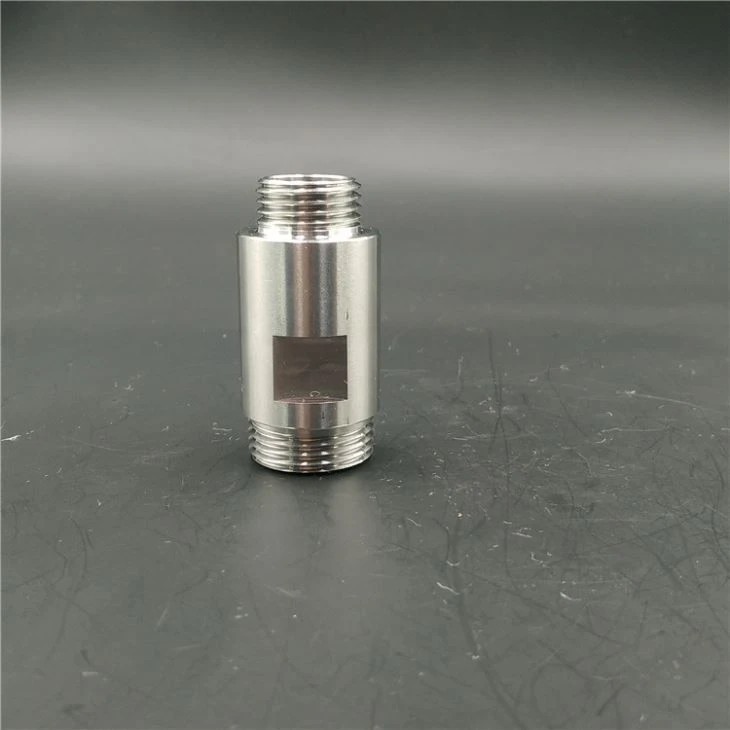
Cam drive feeding mechanism
Oct 16, 2014
Leave a message
Technical realization elements:
5. The purpose of the present utility model is to provide a cam drive feeding mechanism to solve the problems raised in the background art.
6. In order to achieve the above purpose, the present utility model provides the following technical solutions:
7. Cam drive feeding mechanism, including:
8. The feeding assembly, the feeding assembly includes:
9. Discharging parts, used for discharging with the rotation of the crucible on the crucible assembly;
10. Supports, used to support the unwinding parts.
11. As a further technical solution of the present utility model, the discharging part includes:
12. Cam, fixedly installed on the outside of the crucible of the crucible assembly;
13. The opening and closing unit is arranged on the support and slidably connected to it. When the opening and closing unit is opened, the sio2 ring can pass, and when the opening and closing unit is closed, the sio2 ring cannot pass; and
14. A camshaft slidably arranged on the support, one end of the camshaft is matched with the cam, and the other end is matched with the opening and closing unit. When the cam is in contact with the camshaft, the camshaft pushes the opening and closing unit to open.
15. As a further technical solution of the present utility model, the opening and closing unit includes:
16. The first opening and closing page, one end is set in the support and is slidably connected to it;
17. The second opening and closing page, one end is arranged in the support member and slidably connected to it, and is used to cooperate with the first opening and closing page to control the passage of the sio2 ring;
18. Two elastic members are provided. One end of the elastic member is connected with one end of the first opening and closing page extending support member, the other end is connected with the supporting member, and one end of the other elastic member is connected with the second opening and closing page extending support member. One end is connected, and the other end is connected to the support.
19. As a further technical solution of the present invention, the elastic member is a tension spring.
20. As a further technical solution of the present utility model, the supporting member includes:
21. Feeding base, used to install the feeding parts;
22. Cover plate, matched with the feeding base.
23. Compared with the prior art, the beneficial effect of the present invention is that by setting the feeding assembly to synchronously send the sio2 rings into the crucible assembly one by one with the rotation of the crucible assembly, no additional power equipment is required, and the cost is reduced.
Please contact us at zhang@pride-cnc.com